


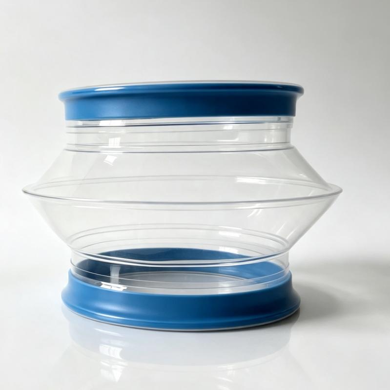
How to Eliminate Load Cell Drift on Loss-in-Weight Feeders: The 80mm Installation Rule
How to Eliminate Load Cell Drift on Loss-in-Weight Feeders: The 80mm Installation Rule
In continuous gravimetric powder dosing—whether feeding battery cathode slurry, pharmaceutical active ingredients, or compounding extruders—precision is everything. A deviation of just a few grams per hour can compromise an entire production batch.
Yet, process engineers frequently battle a frustrating phenomenon: load cell signal drift on Loss-in-Weight (LIW) feeders.
While technicians often blame the weighing sensors or PLC calibration, the root cause is frequently mechanical: improperly installed flexible connectors that transfer parasitic forces and vibration directly onto the weigh scale.
Here is an engineering breakdown of why scale drift happens and how implementing the 80mm Spigot Installation Rule with zero-stiffness connectors permanently resolves force transmission.
1. Why Traditional Connectors Cause Load Cell Signal Noise
A Loss-in-Weight feeder calculates dosing rates by continuously measuring the rate of weight change over time ($-\frac{dm}{dt}$). For the scale to measure micro-changes accurately, the feeder hopper must remain in a state of near-total mechanical isolation.
Traditional flexible sleeves fail this isolation requirement in three ways:
- Mechanical Stiffness & Spring Effect: Rigid rubber, heavy canvas, or improperly tensioned sleeves act like spring mechanisms. As the hopper empties and moves vertically, stiff connectors push back, creating artificial tare weight fluctuations.
- Thermal Expansion Transmission: In extruder feeding setups, high temperatures from the feed throat transfer up the piping. Thermal metal expansion pushes against rigid sleeves, imposing side-loads on sensitive load cell strain gauges.
- Vacuum & Air Displacement Pulses: Downstream vacuum venting or pneumatic pulses cause traditional sleeves to collapse or balloon, creating vertical pressure forces that corrupt scale signals.
2. The Dual-Point Isolation Strategy
To achieve zero force transmission, flexible engineering must isolate the weighing scale at both the material inlet and outlet interfaces.
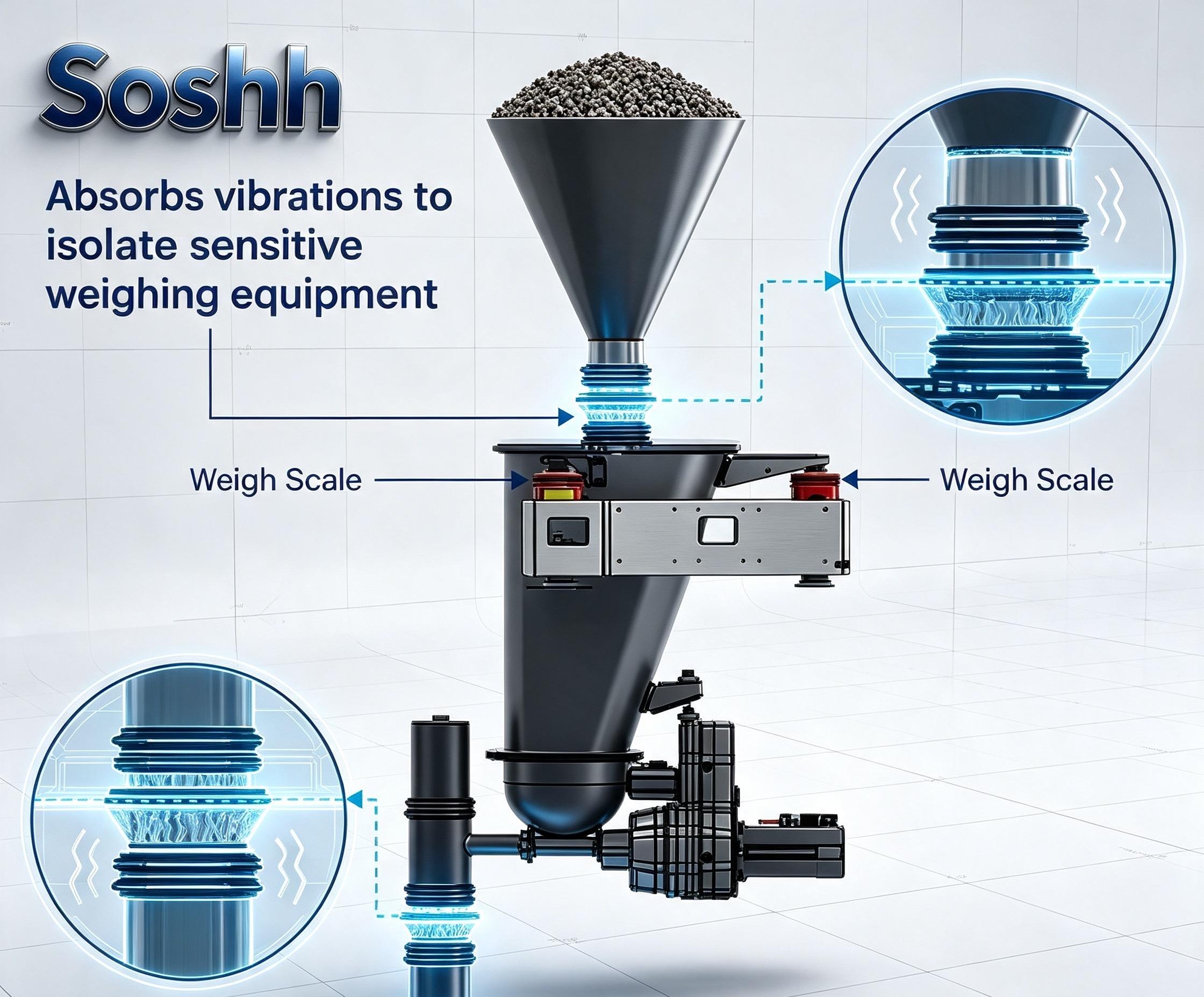
As shown in the application schematic above, a continuous dosing system requires a Dual-Point Isolation System:
- Upper Inlet Isolation: Absorbs shock loads, structural vibrations, and material impact forces from bulk storage silos before they reach the weighing platform.
- Lower Outlet Isolation: Isolates the weigh hopper from downstream extruder vibration, screw feeder motor oscillation, and back-pressure.
By installing flexible bellows with zero spring resistance at both points, the feeder scale floats in a mechanically neutral zone.
3. The Golden Engineering Standard: The 80mm Spigot Gap Rule
Even the most flexible sleeve will transfer forces if installed incorrectly on site. The single most critical dimension in LIW feeder piping is the Installation Gap (IG) between upper and lower mounting spigots.
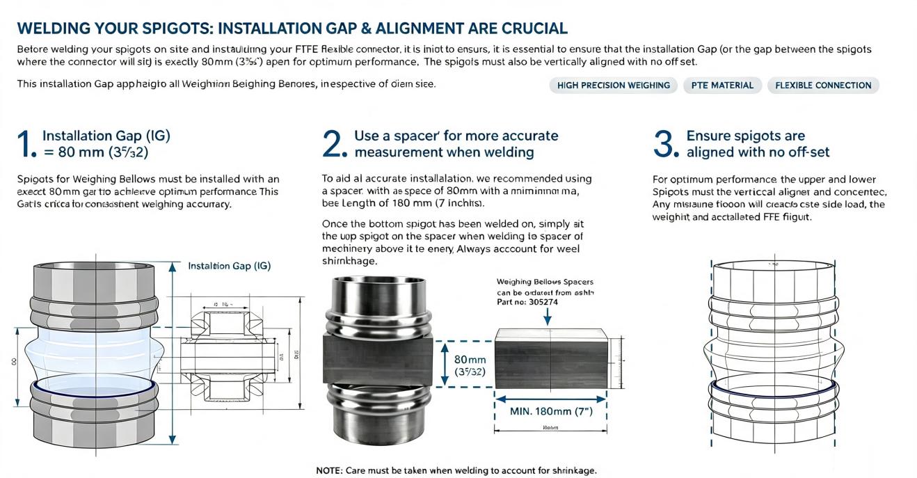
Step 1: Maintain an Exact 80 mm (3 5/32") Installation Gap
The open gap between the stainless steel spigots must measure exactly 80 mm.
- If the gap is < 80 mm: The sleeve becomes pre-compressed, creating an outward bulge that exerts downward force on the scale.
- If the gap is > 80 mm: The sleeve is stretched tight, pulling upward on the load cell.
- At exactly 80 mm: The central bellows ridge sits in its designed relaxed neutral state, delivering maximum multi-axis vibration dampening with zero spring tension.
Step 2: Use an 80 mm Spacer Block During Welding
When welding spigots onto supply lines on site, thermal contraction as welds cool will cause metal shift.
Always clamp a rigid 80 mm Spacer Block (minimum length 180 mm / 7") between the top and bottom spigots during tacking and final welding. Keep the spacer clamped until the weld joint cools completely.
Step 3: Ensure Zero-Offset Vertical Alignment
Upper and lower spigots must be 100% vertically concentric and parallel. Angular misalignment forces the connector into a twisted state, generating persistent shear forces (side loads) that cause permanent baseline drift on scale electronics.
4. Selecting the Optimal Connector Sleeve Material
Eliminating mechanical stress also requires choosing a material that withstands continuous flexing without tearing or shedding contaminants.
| Material Requirement | Traditional Silicone / Rubber | SOSHH® Ether-Grade TPU |
| Mechanical Resistance | Prone to tearing under high flex | 3x–5x higher tear & tensile strength |
| Material Transparency | Opaque (Flow hidden) | 100% Optical Clarity for inspection |
| Particulate Shedding | Degrades & sheds into powder stream | Zero plasticizer migration (FDA compliant) |
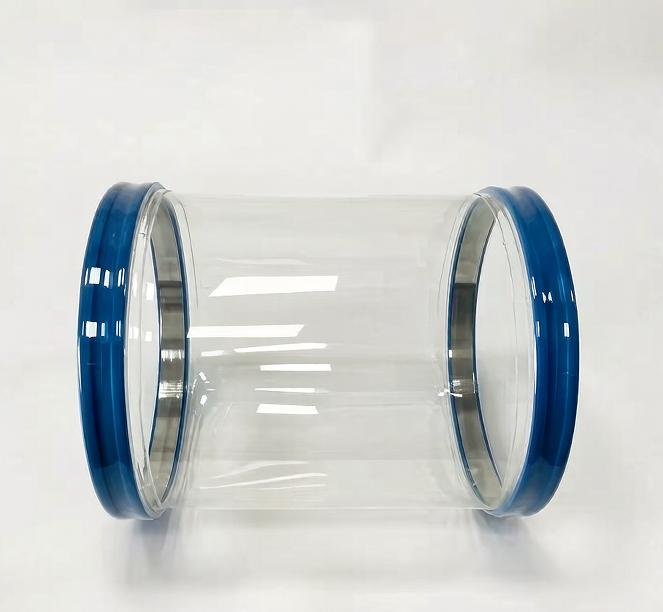
| Sealing System | Hose clamps (Leak-prone) | Tool-Free Snap-In Blue Elastomer Cuffs |
Conclusion: Achieve Uncompromised Dosing Accuracy
Eliminating load cell signal noise does not require redesigning your gravimetric feeding system—it requires eliminating piping tension at the connection points.
By combining the 80mm Spigot Installation Rule with precision-engineered zero-stiffness connectors, you guarantee true weight signal integrity, reduce calibration frequency, and prevent costly off-spec batch production.
🚀 Upgrade Your Feeding Line Connectors
Need 3D STEP models or technical specs for your Loss-in-Weight feeder retrofits?
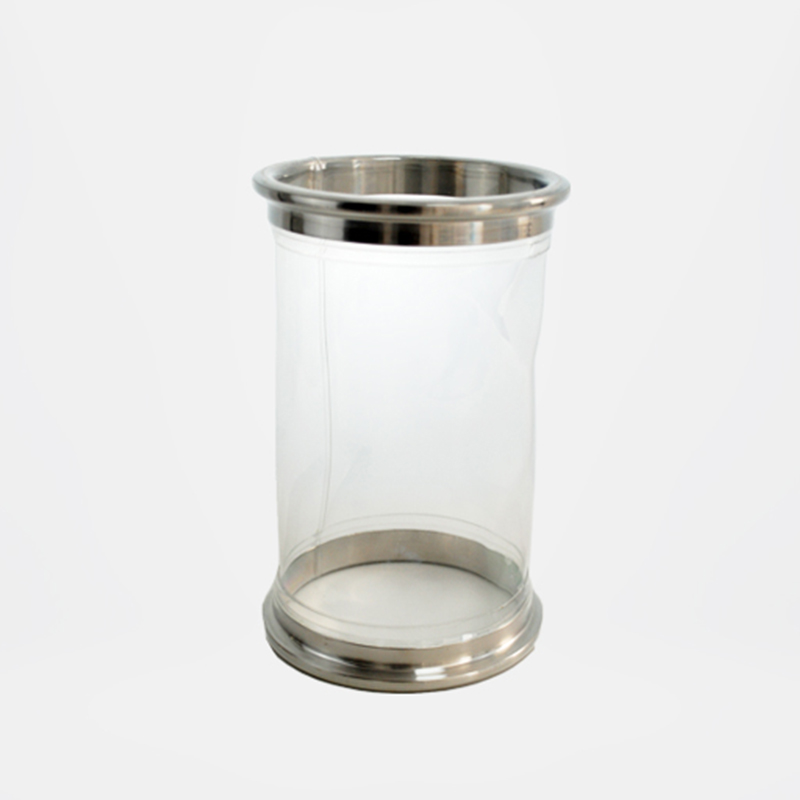
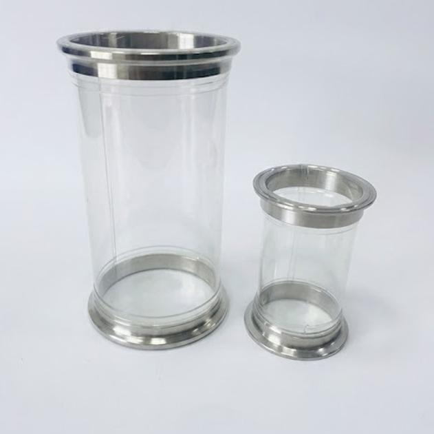
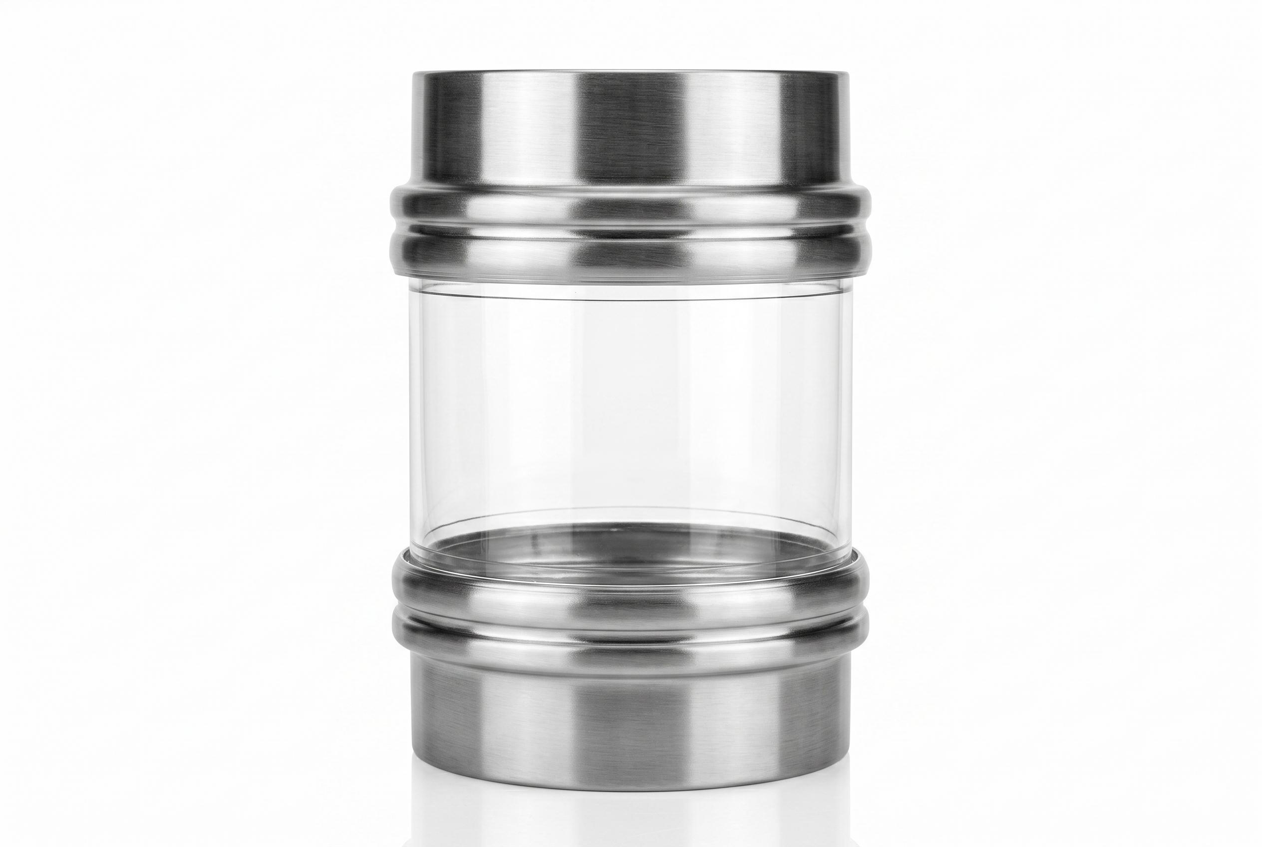
Explore the [SOSHH® SF-ClearFlex™ Transparent TPU Connector]engineered specifically for 80mm spigot installation standards, or request a Free Physical Sample Kit for your engineering lab.
Related Posts