




Why Standard Snap-In Fittings Fail on Pipes Under 100mm & Short Clearances | SOSHH®
Why Standard Snap-In Fittings Fail on Pipes Under 100mm & Short Clearances | SOSHH®
Executive Engineering SummarySnap-in flexible connectors with internal spring-steel bands have revolutionized bulk powder handling on standard process piping. However, when process lines scale down to micro-ingredient dosing under 100 mm (4 in) or face compressed vertical clearances below 80 mm, standard snap-band systems encounter fundamental mechanical limitations. High-tensile spring steel bands cannot deform elastically into micro-bores without permanent yielding or posing finger-crush hazards, while rigid spigots require vertical snap-in clearance that compact machinery simply does not have. This engineering brief examines the mechanical mechanics behind snap-band failure in tight spaces and details how custom high-frequency welded polyether TPU transitions resolve these limitations with zero tooling costs.
The Mechanical Physics Behind Snap-Band Failure Below 100mm (4 Inches)
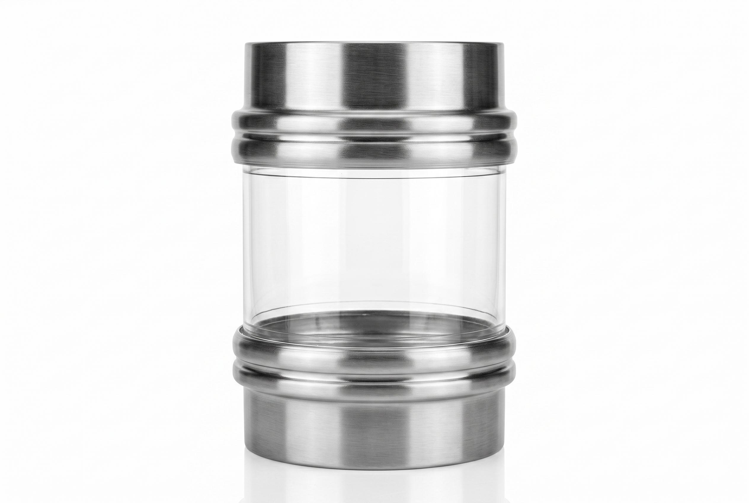
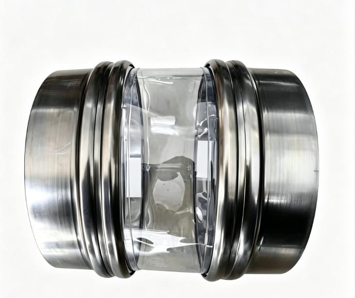
Standard snap-in connector systems depend on a high-tensile spring-steel band encased within a polyurethane cuff. To install or remove the connector, an operator must compress the circular ring into an inverted figure-8 shape, insert it into the rigid spigot, and release it so that outward radial spring tension locks the cuff into the machined spigot groove.
On pipe sizes of 100 mm (4 in) and larger, this design functions reliably. Below 100 mm, the laws of mechanical elasticity and ergonomic clearance present insurmountable barriers.
1. Spring-Steel Elastic Deformation Limits and Permanent Yielding
To compress a circular steel band into a figure-8, the ring must undergo severe bending strain. The mechanical bending stress within the strip is inversely proportional to the bending radius:
Bending Stress = (Young's Modulus x Strip Thickness) / (2 x Bending Radius)
When nominal pipe diameter drops to 76 mm (3 in), 50 mm (2 in), or 25 mm (1 in), the required radius of curvature to form a figure-8 drops below the elastic limit of hardened spring steel. Instead of flexing elastically, the steel band undergoes plastic deformation (permanent bending) or work-hardening fracture. Once bent out of round, the band loses its uniform radial seating force, leading to localized gaps and fine powder blow-by under continuous line pressure.
2. Physical Hand Clearance and Operator Ergonomics
In a 100 mm diameter bore, the total cross-sectional area is approximately 78.5 square centimeters. After an operator inserts two hands or four fingers to snap the band inward, sufficient free area remains to maneuver.
In a 50 mm (2 in) or 38 mm (1.5 in) bore, the opening is narrower than an operator's fist. It is physically impossible to reach fingers inside the tube to snap the band into a recessed groove without specialized pry tools, which run the risk of puncturing the thin 1.0 mm TPU cuff and creating unacceptable pinch-point safety risks under plant health and safety guidelines.
The Short-Clearance Trap: Why Grooved Spigots Fail Below 80mm Headroom
Standard snap-in connection designs do not just require radial bore width; they demand generous axial headroom.
Standard Snap-In Spigot Interface (Requires 80mm to 120mm Minimum Gap)
======================================================================
  [ Top Equipment Flange / Rotary Valve ]
  |-------------------------------------|
  |  Upper Steel Spigot (37mm to 52mm)  | ===> Fixed rigid metal height
  |=====================================|
  |  Snap Groove Seating Zone           |
  |.....................................|
  :  Active Flexible Sleeve Span        : ===> Requires minimum 80mm+ for
  :  (Needed for stroke and snap-out)   :      elastic snap-out action
  |.....................................|
  |  Snap Groove Seating Zone           |
  |=====================================|
  |  Lower Steel Spigot (37mm to 52mm)  | ===> Fixed rigid metal height
  |-------------------------------------|
  [ Bottom Receiving Hopper / Feeder   ]
1. Mandatory Vertical Stroke for Installation
A standard spigot head measures 37 mm to 52 mm in vertical height, with a machined internal groove located 15 mm to 25 mm from the lip. To remove a snap-band connector, the sleeve must have enough axial slack to allow an operator to push the bottom cuff upward, fold the band, and clear the steel lip.
When upstream equipment (such as a rotary airlock or slide gate) sits directly above a loss-in-weight feeder hopper, physical flange-to-flange clearance is frequently squeezed to 30 mm to 55 mm. In this footprint, the two opposing steel spigot lips would touch or collide, leaving zero physical space for an active flexible sleeve.
2. Deep Creasing, Choking, and Rapid Fatigue Cracking
When a standard 100 mm long flexible sleeve is compressed into a tight vertical gap of 40 mm to 50 mm, the excess elastomer buckles outward or inward. This creates sharp, permanent horizontal creases.
- Material Choking: Inward folds create internal ledges that trap product, causing fine powders (such as baby milk powder, starch, or carbon black) to accumulate, cake, and spoil.
- Flex-Fatigue Slicing: During continuous vibratory screening or feeder agitation, these tight creases become stress-concentration nodes. High-frequency oscillating shear causes the TPU wall to crack and split along the crease lines within weeks.
Technical Comparison: Standard Snap-Band vs. SOSHH Custom Solutions
| Engineering Feature | Standard Snap-Band Connector Systems | SOSHH Custom Engineered Flexible Transitions |
|---|---|---|
| Minimum Bore Diameter | Strictly limited to 100 mm (4.0 in) | Down to 25 mm (1.0 in) ID for micro-dosing lines |
| Minimum Installed Height | 80 mm to 100 mm minimum face-to-face gap | Down to 30 mm (1.2 in) short-clearance profiles |
| Duct Geometry Options | Circular profiles only | Round, square, rectangular, conical, and eccentric |
| Installation Interface | Proprietary grooved steel weld spigot | Sanitary Tri-Clamp, rolled-edge clamps, or bolt flanges |
| Tooling & Mold Setup Fees | Expensive custom mold tooling required | Zero tooling fees (CNC digital acoustic cutting) |
| Load Cell Decoupling | High lateral stiffness; risks scale drift | Ultra-soft PU05 (0.5 mm) for zero reactive force |
| Explosion Safety (ATEX) | Optional anti-static material | Permanent anti-static polyether TPU (10^6 to 10^9 Ohm) |
Engineering Solutions for Micro-Bore and Tight Headroom Applications
To solve containment challenges where snap-bands cannot operate, SOSHH utilizes precision CNC plotting, ultrasonic profile slicing, and modular dielectric high-frequency thermal welding.
       [ Micro-Bore / Short-Clearance Engineered Interfaces ]

   (A) Micro-Bore Sanitary TC       (B) Ultra-Short Dosing Sleeve
    ===========================      =============================
        [ Tri-Clamp Ferrule ]             [ Upper Equipment Lip ]
           ||             ||                | |                 | |
       /===||=============||===\            | |                 | |
      |     \             /     |         ==[=]=================[=]== Rolled-Edge Clamp
      |      \  Polyether/      |         |     Low-Profile     |
      |       \   TPU   /       |         |     0.5mm PU05      | (30mm to 55mm Span)
      |        |       |        |         |     Zero Drift      |
      |        |  ID   |        |         ==[=]=================[=]== Rolled-Edge Clamp
      |        | 25mm  |        |           | |                 | |
       \=======|       |=======/            | |                 | |
        [ Sanitary TC Ferrule ]           [ Loss-in-Weight Feeder ]
1. Micro-Bore Dosing Sleeves (25 mm to 89 mm) with Tri-Clamp Ferrules
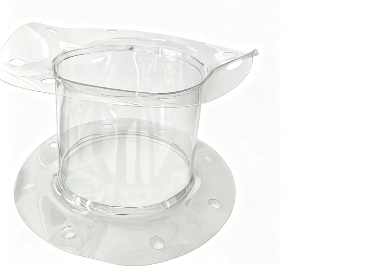
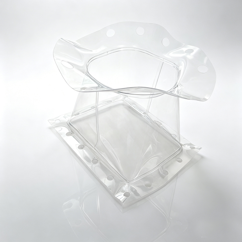
For micro-ingredient dosing nozzles, twin-screw pharmaceutical feeders, and additive injection ports, SOSHH fabricates custom polyether TPU sleeves starting at 25 mm ID.
- Sanitary Tri-Clamp End Connections: Integrates over-molded or thermally fused 304/316L Tri-Clamp compatible ferrules (TC 50.5 mm or TC 64.0 mm). Operators clamp and unclamp the joint in seconds using standard sanitary wing-nut clamps without reaching inside the pipe.
- Smooth-Band Hose Clamp Cuffs: For plain pipe spuds, sleeves are engineered with straight plain cuffs secured by SOSHH German-style smooth-band clamps with rolled outer edges, ensuring high sealing pressure without pinching the 1.0 mm sleeve wall.
2. Ultra-Low-Profile Short-Clearance Feeder Sleeves (30 mm to 55 mm)
When vertical headroom is restricted to 30 mm to 55 mm between rotary airlocks and loss-in-weight feeders, SOSHH supplies custom pre-formed cylindrical or single-convolution sleeves.
- PU05 Ultra-Soft Polyether Film (0.50 mm): Delivers structural hoop strength to contain pressure surges up to +0.2 bar while providing low flexural rigidity.
- Zero Load-Cell Reactive Force: The 0.5 mm wall absorbs axial vibration and thermal movement without transmitting mechanical tension onto sensitive load cells, protecting gravimetric feeding accuracy.
3. Non-Standard Square-to-Round and Off-Center Conical Funnels
Interfacing square-flanged bin discharges with round pneumatic conveying lines traditionally required expensive fabricated sheet metal transition chutes that introduce product hang-up ledges.
- CAD-Guided Dielectric Welding: Fabricates seamless transitions from square/rectangular inlets (up to 1200 mm) to circular outlets with steep internal cone angles.
- Mirror-Smooth Internal Bore: With an internal surface finish of Ra < 0.4 um, powders discharge via natural mass flow without bridging, dead zones, or batch-to-batch contamination.
Installation Sizing Rules for Process Engineers
When ordering custom flexible sleeves for tight spaces or non-standard diameters, use these formulas to calculate correct fabrication dimensions:
Rule 1: Micro-Bore Clamp-Style Sleeve Diameter
To prevent sleeve bunching under the band clamp:
Fabrication Sleeve ID = Equipment Spigot OD + (0.5 mm to 1.0 mm)
Example: For a stainless tube with an outside diameter of 60.5 mm, specify an internal sleeve diameter of 61.0 mm to 61.5 mm. This allows the cuff to slide over the spud without excessive material slack beneath the clamp band.
Rule 2: Short-Clearance Vertical Length Calculation
To prevent vertical creasing and material choking:
Installed Sleeve Length = Static Flange Gap - (0.5 x Total Axial Stroke)
Example: If the static metal-to-metal gap between chute flanges is 50 mm, and the scale vibrator produces +/- 4 mm of vertical displacement, specify a sleeve length of 48 mm. This keeps the TPU wall straight under maximum upward compression.
Frequently Asked Technical Questions (Engineering RFQs)
Q1: Why not simply use silicone hose cut to length for micro-bores?
- Failure Mode: Commercial silicone hose is stiff, opaque, and prone to tear propagation. Once a minor surface nick occurs from a clamp edge, vibration causes the tear to run across the entire wall. Silicone also sheds siloxane oils under friction, failing purity standards in dry powder dosing.
- SOSHH Solution: Pure virgin polyether TPU provides high tear strength (up to 550 N/cm) and full optical clarity, outlasting silicone by 3x to 5x on continuous micro-feeders.
Q2: Can SOSHH custom micro-bore sleeves operate under continuous vacuum?
- Vacuum Capability: Straight 1.0 mm TPU sleeves handle moderate suction down to -200 mbar at small diameters (25 mm to 50 mm) without collapsing due to their natural hoop stiffness. For vacuum lines operating down to -1000 mbar, SOSHH integrates welded 316 stainless steel external rings to prevent inward wall collapse.
Q3: Are there tooling or setup charges for custom dimensional transitions?
- Zero Tooling Policy: No. Because SOSHH utilizes digital CAD acoustic profile plotting and modular high-frequency welding bars, there are no fixed die-cutting or injection mold tooling charges. Prototypes and production runs are priced purely on material, hardware, and fabrication time.
Q4: How do custom transitions handle explosive ATEX dust atmospheres?
- Static Dissipation: Standard clear TPU is an electrical insulator. For combustible dust processing (such as sugar, starch, toner, or battery cathode powders), SOSHH manufactures custom micro-bore and transition sleeves from permanently anti-static polyether TPU (surface resistivity 10^6 to 10^9 Ohm), ensuring static charges discharge to grounded piping.
Next Steps: Fast-Track Your Custom Sizing Verification
If your process line features pipe bores below 100 mm, vertical headroom below 80 mm, or irregular rectangular chutes where standard off-the-shelf snap-in systems cannot fit, explore our complete technical parameters and order form:
- Review full material data, size matrices, and CAD templates on our primary product page:Custom Non-Standard Flexible Connectors: Micro-Bore, Short-Clearance & Square-to-Round Transitions
- Send your hand sketch, CAD drawing, or equipment model to our engineering desk at amin@soshh.com to receive a dimensioned 2D Production Traveler and material compliance dossier within 24 hours.
Tags:
- TPU flexible connections
- Dust-free powder transfer solutions
- Dust-tight Flexible Connectors
- Connector Replacement
- Custom Diameter & Length Sleeves
- Custom PU Flexible Connectors
- Custom Fabricated TPU Bellows
- Custom Conical Powder Sleeves
- Custom Size PU Bellows
- Engineering Guides
- Food Grade TPU Sleeve
- FDA 21 CFR 177.2600
Related Posts