




Weld-On Steel Spigots for Snap-In Flexible Connectors | Engineering Specs & Size Chart
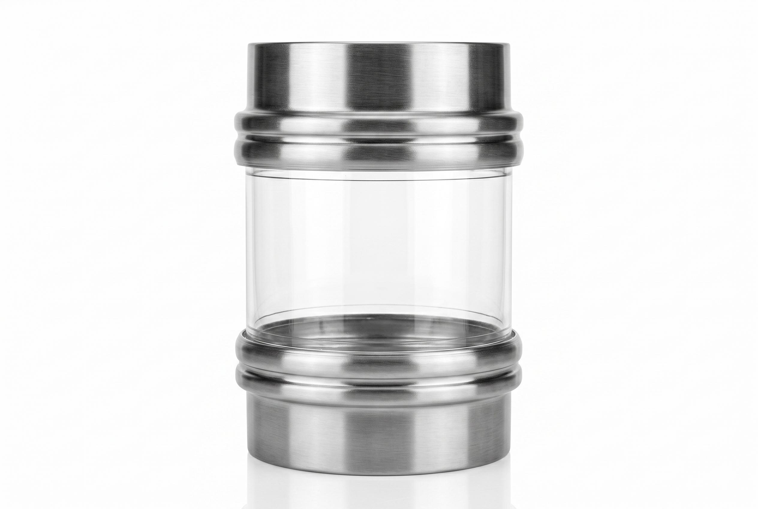
Entity-Dense Summary: SOSHH weld-on stainless steel spigots are the rigid docking rings that snap-in flexible connector cuffs lock onto, forming a 100% dust-tight, crevice-free seal between vibrating process equipment and conveying lines. Precision-machined in SS304 (1.4301) and SS316L (1.4404) with an internal 2B finish (Ra < 0.8 µm) or electro-polished finish (Ra < 0.4 µm), every spigot is verified to ISO 2768-m tolerances and ships with an EN 10204 3.1 material test certificate. Standard heights are 50 mm and 90 mm across Ø102–804 mm diameters, featuring a tapered seating face and zero-hole sanitary profiles.
Why the Spigot Is the Foundation of a Dust-Tight Seal
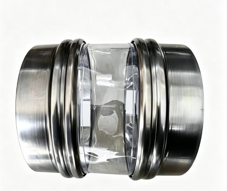
A flexible connector is only as reliable as the metal spigot it snaps onto. The sleeve cuff seats directly into the spigot’s machined outer groove. The geometric precision of that seating surface — roundness, taper angle, surface roughness, and metallurgy — determines whether your connection remains 100% dust-tight under 20–30 Hz continuous vibration or leaks fine micronized powder into the production room.
- Precision Roundness: The cuff engages evenly around the full 360° circumference, preventing stress peaks.
- Tapered Sealing Face: The lip profile locks the cuff progressively tighter under vibration, eliminating the need for clamps.
- Certified Metallurgy: SS304 for dry powder/food handling; SS316L for high-salinity, dairy, and hot caustic CIP washdown.
- 100% Traceability: Every production batch ships with an authentic EN 10204 3.1 Inspection Certificate.
Material & Surface Engineering Specifications
- Steel Grades: AISI 304 (1.4301) standard / AISI 316L (1.4404) for pharmaceutical & aggressive CIP environments
- Internal Surface Finish: Standard 2B (Ra < 0.8 µm) / Electro-polished sanitary grade (Ra < 0.4 µm)
- Machining Tolerance: ISO 2768-m medium class (100% dimensional inspection)
- Standard Wall Thickness: 2.0 mm structural wall
- Material Certification: EN 10204 Type 3.1 Inspection Certificate included with heat number tracking
- Height Configurations: 50 mm standard compact / 90 mm extended weld-buffer design
Tapered Sealing Principle — Why the Cuff Never Disengages
The spigot’s outer rim is precision-turned with a controlled taper: the leading edge diameter is slightly larger than the groove seating base. When the snap-in TPU sleeve cuff is pushed into place, this profile generates continuous radial hoop tension. Under operational vibration (such as gyratory screeners operating at 20–30 Hz), this mechanical tension continuously presses outward against the internal groove, creating a self-locking, dust-tight containment barrier.
Standard Dimension Tables
Series A — 50 mm Height Standard Spigots
Engineered for compact installation gaps and standard vibratory sifter inlets and discharges. (18 standard sizes)
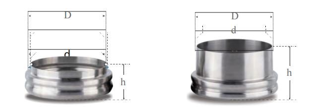
| SN | Outer Ø D (mm) | Inner Ø d (mm) | Wall T (mm) | Height h (mm) | AISI 304 Part Number | AISI 316L Part Number | Matching Sleeve ØD |
|---|---|---|---|---|---|---|---|
| 1 | 102 | 98 | 2.0 | 50 | SF10250304SS | SF10250316L | Ø102 mm (4") |
| 2 | 152 | 148 | 2.0 | 50 | SF15250304SS | SF15250316L | Ø152 mm (6") |
| 3 | 154 | 150 | 2.0 | 50 | SF15450304SS | SF15450316L | Ø152 / Special Transition |
| 4 | 159 | 155 | 2.0 | 50 | SF15950304SS | SF15950316L | Ø159 mm (DN150) |
| 5 | 204 | 200 | 2.0 | 50 | SF20450304SS | SF20450316L | Ø204 mm (8") |
| 6 | 219 | 215 | 2.0 | 50 | SF21950304SS | SF21950316L | Ø219 mm (DN200) |
| 7 | 254 | 250 | 2.0 | 50 | SF25450304SS | SF25450316L | Ø254 mm (10") |
| 8 | 273 | 269 | 2.0 | 50 | SF27350304SS | SF27350316L | Ø273 mm (DN250) |
| 9 | 304 | 300 | 2.0 | 50 | SF30450304SS | SF30450316L | Ø304 mm (12") |
| 10 | 325 | 321 | 2.0 | 50 | SF32550304SS | SF32550316L | Ø325 mm (DN300) |
| 11 | 354 | 350 | 2.0 | 50 | SF35450304SS | SF35450316L | Ø354 mm (14") |
| 12 | 377 | 373 | 2.0 | 50 | SF37750304SS | SF37750316L | Ø377 mm (15") |
| 13 | 404 | 400 | 2.0 | 50 | SF40450304SS | SF40450316L | Ø404 mm (16") |
| 14 | 454 | 450 | 2.0 | 50 | SF45450304SS | SF45450316L | Ø454 mm (18") |
| 15 | 504 | 500 | 2.0 | 50 | SF50450304SS | SF50450316L | Ø504 mm (20") |
| 16 | 554 | 550 | 2.0 | 50 | SF55450304SS | SF55450316L | Ø554 mm (22") |
| 17 | 604 | 600 | 2.0 | 50 | SF60450304SS | SF60450316L | Ø604 mm (24") |
| 18 | 654 | 650 | 2.0 | 50 | SF65450304SS | SF65450316L | Ø654 mm (26") |
| 19 | 704 | 700 | 2.0 | 50 | SF70450304SS | SF70450316L | Ø704 mm (28") |
| 20 | 754 | 750 | 2.0 | 50 | SF75450304SS | SF75450316L | Ø754 mm (30") |
| 21 | 804 | 800 | 2.0 | 50 | SF80450304SS | SF80450316L | Ø804 mm (32") |
Series B — 90 mm Height Extended Spigots
Specified when a larger Heat-Affected Zone (HAZ) buffer is required during orbital TIG welding, or where pipe flange clearances demand extra reach.
| SN | Outer Ø D (mm) | Inner Ø d (mm) | Wall T (mm) | Height h (mm) | AISI 304 Part Number | AISI 316L Part Number | Matching Sleeve ØD |
|---|---|---|---|---|---|---|---|
| 1 | 102 | 98 | 2.0 | 90 | SF10290304SS | SF10290316L | Ø102 mm (4") |
| 2 | 152 | 148 | 2.0 | 90 | SF15290304SS | SF15290316L | Ø152 mm (6") |
| 3 | 154 | 150 | 2.0 | 90 | SF15490304SS | SF15490316L | Ø152 / Special Transition |
| 4 | 159 | 155 | 2.0 | 90 | SF15990304SS | SF15990316L | Ø159 mm (DN150) |
| 5 | 204 | 200 | 2.0 | 90 | SF20490304SS | SF20490316L | Ø204 mm (8") |
| 6 | 219 | 215 | 2.0 | 90 | SF21990304SS | SF21990316L | Ø219 mm (DN200) |
| 7 | 254 | 250 | 2.0 | 90 | SF25490304SS | SF25490316L | Ø254 mm (10") |
| 8 | 273 | 269 | 2.0 | 90 | SF27390304SS | SF27390316L | Ø273 mm (DN250) |
| 9 | 304 | 300 | 2.0 | 90 | SF30490304SS | SF30490316L | Ø304 mm (12") |
| 10 | 325 | 321 | 2.0 | 90 | SF32590304SS | SF32590316L | Ø325 mm (DN300) |
| 11 | 354 | 350 | 2.0 | 90 | SF35490304SS | SF35490316L | Ø354 mm (14") |
| 12 | 377 | 373 | 2.0 | 90 | SF37790304SS | SF37790316L | Ø377 mm (15") |
| 13 | 404 | 400 | 2.0 | 90 | SF40490304SS | SF40490316L | Ø404 mm (16") |
| 14 | 454 | 450 | 2.0 | 90 | SF45490304SS | SF45490316L | Ø454 mm (18") |
| 15 | 504 | 500 | 2.0 | 90 | SF50490304SS | SF50490316L | Ø504 mm (20") |
| 16 | 554 | 550 | 2.0 | 90 | SF55490304SS | SF55490316L | Ø554 mm (22") |
| 17 | 604 | 600 | 2.0 | 90 | SF60490304SS | SF60490316L | Ø604 mm (24") |
| 18 | 654 | 650 | 2.0 | 90 | SF65490304SS | SF65490316L | Ø654 mm (26") |
| 19 | 704 | 700 | 2.0 | 90 | SF70490304SS | SF70490316L | Ø704 mm (28") |
| 20 | 754 | 750 | 2.0 | 90 | SF75490304SS | SF75490316L | Ø754 mm (30") |
| 21 | 804 | 800 | 2.0 | 90 | SF80490304SS | SF80490316L | Ø804 mm (32") |
Custom CNC Turning: Available for non-standard process pipes from Ø100 mm to Ø1000+ mm. Full cross-reference dimensions are available in our Standard Size Database.
Sanitary Sealing Profile & Grounding Options
- Zero-Hole Sanitary Execution (Default): SOSHH spigots are supplied with a smooth, continuous rim without pre-drilled holes, eliminating bacteria collection points during food/CIP washdowns.
- Optional 6 mm Release Hole: For retrofits utilizing specialized disassembly tools, a precision 6 mm hole can be machined into the side ridge upon request.
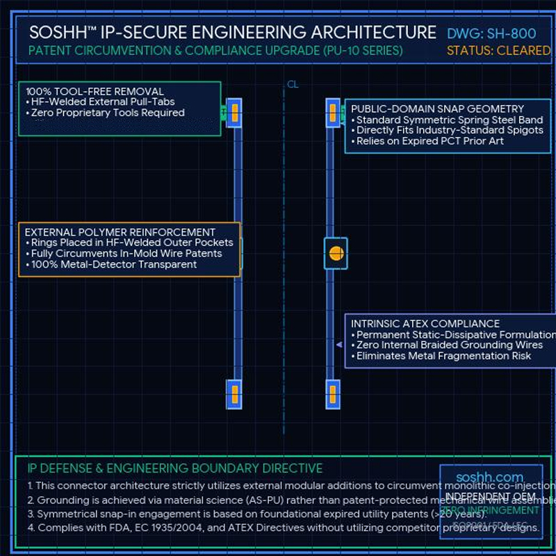
- Static Dissipative Grounding: For combustible dust environments (ATEX Zones 20/21/22), both weld-on spigots should be bonded via copper grounding straps. When paired with our PUAS Anti-Static Sleeve (< 10⁹ Ω), static charges are bled into earth ground.
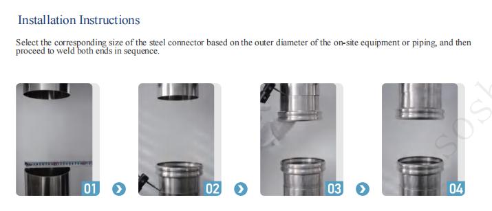
On-Site Installation Protocol (Zero-Leakage Weld)
- Measure Existing Pipe: Confirm the pipe OD and out-of-roundness using calipers or a Pi tape.
- Align & Tack: Position the straight weld tail of the spigot flush against the pipe. Ensure concentricity and tack weld at 4 quadrant points.
- Full Penetration Weld: Complete a continuous, gas-shielded TIG weld. Grind the internal weld bead flush (Ra < 0.8 µm) to prevent powder stagnation.
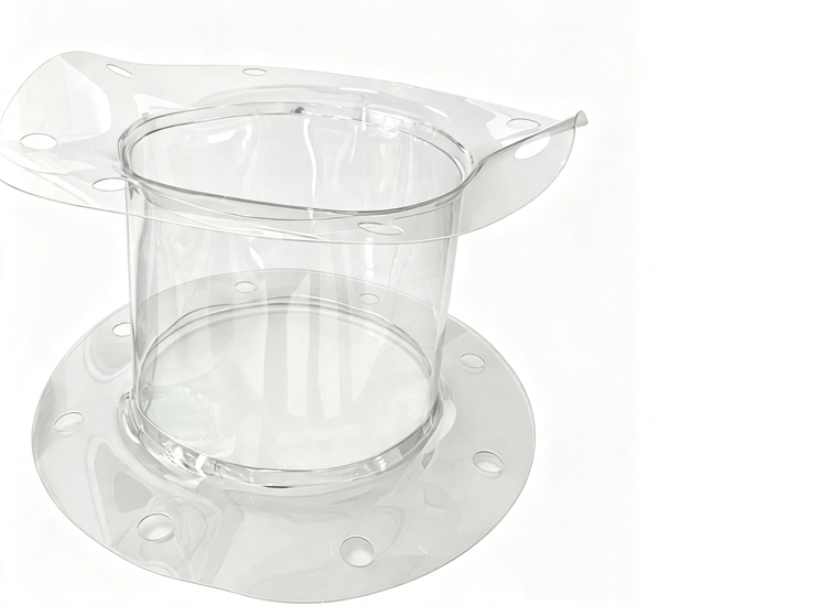
- Snap-In Assembly: Compress the TPU flexible sleeve into an inward shape, insert into the spigot channel, and release. The internal snap-band locks into the groove in under 30 seconds without tools.
Frequently Asked Questions
Q1: What is the mechanical difference between a spigot and an ordinary pipe stub?
An ordinary pipe stub lacks the precision-turned groove and tapered profile required to lock a snap-in band. SOSHH spigots provide the exact channel geometry and surface finish required to guarantee a dust-tight seal under continuous vibration.
Q2: Should I select the 50 mm or 90 mm height?
Choose 50 mm for compact installations, short chutes, or where vertical space is constrained. Choose 90 mm when site welding generates significant heat that could reach nearby sensors or seals, or where thermal distortion must be isolated from the docking groove.
Q3: Do you supply EN 10204 3.1 certificates?
Yes. Every order is traceable to the mill heat number and ships with a verified EN 10204 3.1 material test certificate detailing the chemical composition and mechanical properties of the SS304 or SS316L alloy.
Q4: Can you fabricate custom spigots to fit non-standard pipes?
Yes. Our CNC workshop machines custom wall thicknesses, extended lengths, and intermediate diameters (e.g., Ø133 mm, Ø168 mm) with zero tooling fees.
Request a 2D Spigot Drawing Within 24 Hours
Submit three parameters to our engineering desk for immediate 2D outline verification:
- [ ] Required Spigot OD: Process pipe or channel outer diameter (mm)
- [ ] Total Height: 50 mm standard or 90 mm extended
- [ ] Stainless Steel Metallurgy: AISI 304 or AISI 316L
Email: amin@soshh.com | WhatsApp / Phone: +86 13567045023
Subject line: RFQ — Steel Spigot — [Company] — [ØD × h]
Engineering Resources & Quick Links
- Standard Diameters & Sleeve Combinations: Browse the Standard Size Database
- Step-by-Step Measurement Guide: How to Measure Spigot OD & Installation Gap
- Standard Heavy-Duty Sleeves: PU-10 Clear Snap-In Flexible Connector
Related Posts