





SF Internal Snap-On Flexible Connectors: The Complete Engineering & Procurement Guide for Zero-Leak Powder Handling
Direct-Answer Block
Q: How does the SF internal snap-on connector achieve a dust-tight seal without clamps or bolts?
A: The seal comes from three components working together. A spring-steel band is hot-melt bonded inside the sleeve wall at each end, and a sealing ring sits at the cuff. When the cuff is compressed and inserted into the welded spigot, the band recoils and applies a radial pre-tension against the spigot’s inner wall. The sleeve then elastically snaps back to grip the groove, producing a dust-tight seal with no external clamp compression and no tools.
The Three-Part System
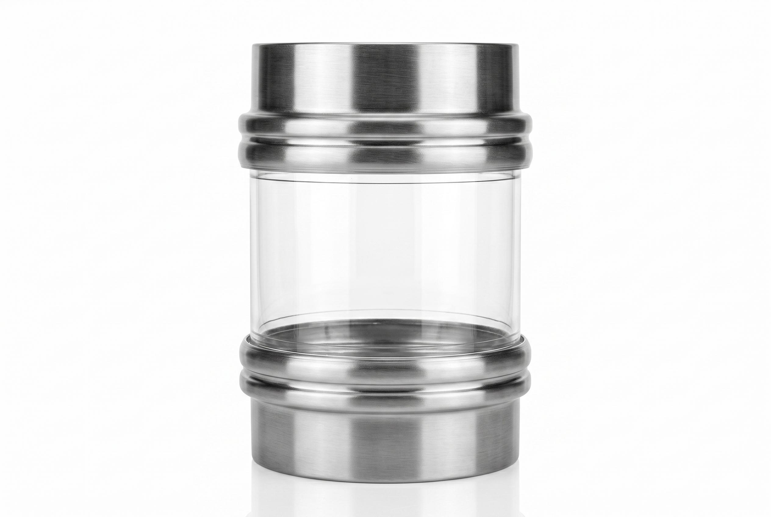
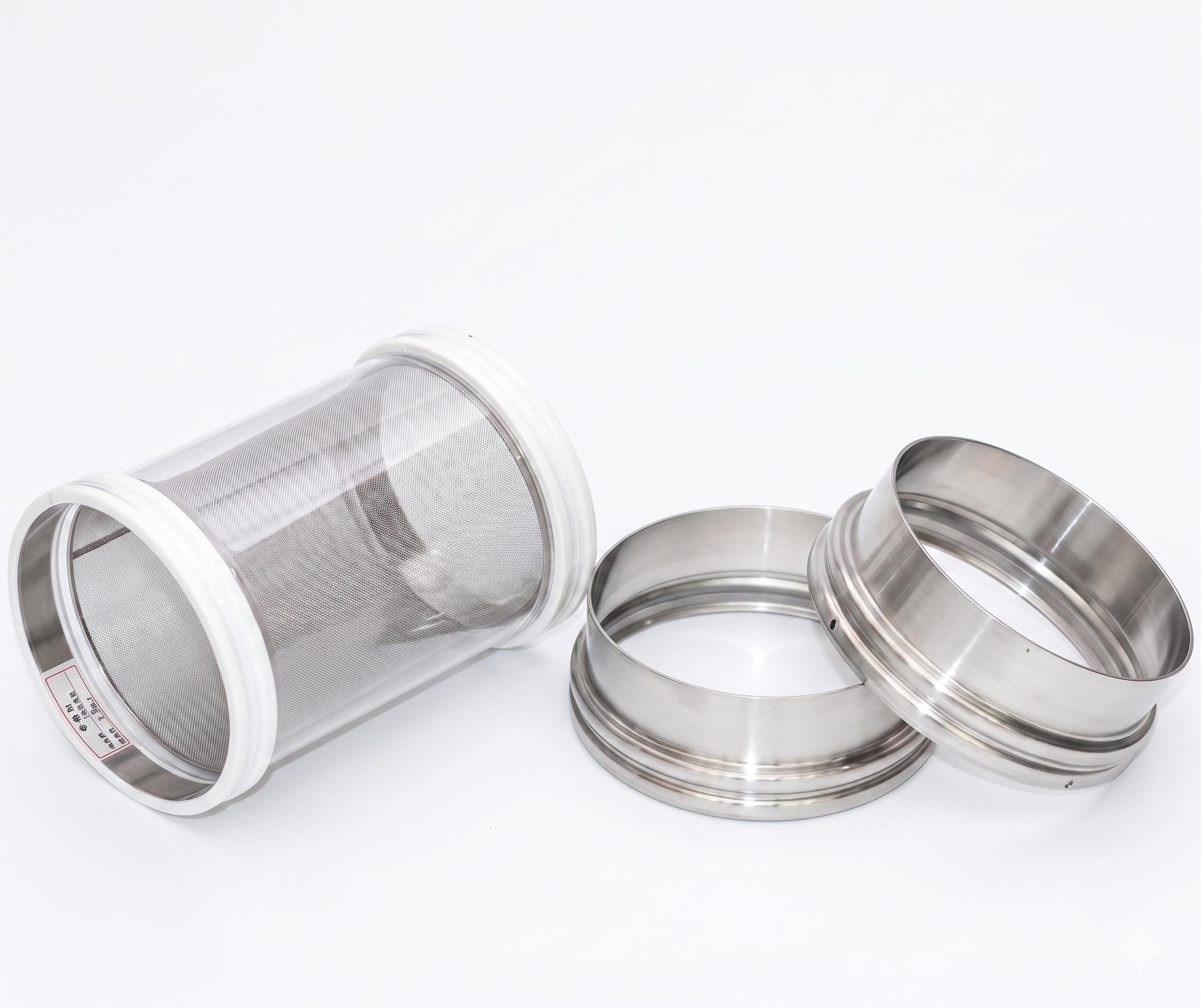
Every SF snap-on connector is a matched system of three components. All three must be specified together — the sleeve alone cannot seal without the correct spigot.
| COMPONENT | MATERIAL / FUNCTION | ROLE |
|---|---|---|
| Sleeve | Clear polyether TPU, 1.0 mm wall | Flexes to absorb vibration, offset, and pressure |
| Spigot (steel head) | 304L / 316L stainless, polished | Welded once to the pipe; provides the fixed sealing groove |
| Snap engagement | Spring-steel band + sealing ring, hot-melt bonded | Applies radial pre-tension for the dust-tight seal |
The engagement mechanism is what separates the SF from hose-clamp and flange interfaces: retention is mechanical engagement inside a groove, not radial compression of the flexing wall.
How the Seal Works (Step by Step)
- The spigot is welded once. A sanitary stainless steel spigot is welded to each equipment outlet. This is a one-time capital step.
- The sleeve cuff is compressed. The operator squeezes the cuff inward by hand.
- The cuff is inserted into the spigot. With the cuff compressed, the end seats into the spigot’s bore.
- The band recoils. The spring-steel band, hot-melt bonded inside the sleeve wall, rebounds to apply radial pre-tension against the spigot’s inner wall.
- The seal is set. The sealing ring and the recoil force produce a dust-tight, vibration-tolerant seal — no bolts, no clamps, no tools.
Removal is the reverse: compress the cuff and withdraw the sleeve through the spigot’s 6 mm removal hole.
The Welded Spigot: Specifications
The spigot is the fixed half of the system. It is supplied in two heights, both in 304L or 316L stainless, with inner and outer surfaces polished to prevent damage to the sleeve.
| SPIGOT SPEC | 50 MM HEIGHT | 90 MM HEIGHT |
|---|---|---|
| Material | 304L / 316L | 304L / 316L |
| Surface | Inner + outer polished | Inner + outer polished |
| Removal hole | 6 mm side hole | 6 mm side hole |
| Diameter range | Ø154–804 mm | Ø102–354 mm |
Spigot Diameter Table (D = outer diameter, d = inner bore)
50 mm height — 18 standard sizes:
| SN | D (MM) | D (MM) | SN | D (MM) | D (MM) |
|---|---|---|---|---|---|
| 1 | 154 | 150 | 10 | 404 | 400 |
| 2 | 159 | 155 | 11 | 454 | 450 |
| 3 | 204 | 200 | 12 | 504 | 500 |
| 4 | 219 | 215 | 13 | 554 | 550 |
| 5 | 254 | 250 | 14 | 604 | 600 |
| 6 | 273 | 269 | 15 | 654 | 650 |
| 7 | 304 | 300 | 16 | 704 | 700 |
| 8 | 325 | 321 | 17 | 754 | 750 |
| 9 | 354 | 350 | 18 | 804 | 800 |
90 mm height — 6 standard sizes:
| SN | D (MM) | D (MM) |
|---|---|---|
| 19 | 102 | 97 |
| 20 | 152 | 148 |
| 21 | 204 | 200 |
| 22 | 254 | 250 |
| 23 | 304 | 300 |
| 24 | 354 | 350 |
Selection rule: match the spigot outer diameter (D) to your equipment or pipe outer diameter, then weld both ends in sequence. The sleeve is specified to the same diameter reference.
Standard Sizing Matrix
The SF sleeve is available in a 20-diameter × 19-length matrix — 380 standard combinations, plus full custom sizes with a minimum length of 80 mm.
| PARAMETER | STANDARD RANGE | INCREMENTS |
|---|---|---|
| Diameter (D) | Ø102, 152, 159, 204, 219, 254, 273, 304, 325, 354, 377, 404, 454, 504, 554, 604, 654, 704, 754, 804 mm | — |
| Length (CL) | 100, 150, 200, 250, 300, 350, 400, 450, 500, 550, 600, 650, 700, 750, 800, 850, 900, 950, 1000 mm | 50 mm |
| Custom | Any dimension, minimum 80 mm | — |
What D and CL Actually Measure
- D (diameter) = the distance between the two spigot welding points on the equipment — approximately equal to the sleeve diameter.
- CL (length) = the installed face-to-face length, excluding the sealing-ring areas at both ends.
This distinction matters: ordering the wrong reference (inside vs outside, or including cuffs) is the single most common procurement error. See the How to Measure & Size guide for a full measurement walkthrough.
Part Number System
Specify any SF sleeve with the standardized code:
PU10 - D{Ø} - CL{length}
| CODE SEGMENT | MEANING | EXAMPLE |
|---|---|---|
| PU10 | 1.0 mm clear polyether TPU, standard grade | PU10 |
| D{Ø} | Sleeve diameter in mm | 204 |
| CL{length} | Installed length in mm | 300 |
Example: PU10-204-300 = Ø204 mm × 300 mm, standard clear polyether TPU, SF internal snap-on.
Material variants use different prefix codes (see below). The full matrix is listed in the Standard Size Database.
Material Options
The SF connector is available in five material grades. Choose by operating condition, not by price.
| MATERIAL | BEST FOR | COLOR | WALL | TEMP RANGE | SURFACE RESISTIVITY |
|---|---|---|---|---|---|
| Polyether TPU (PU-10) | Most common powder handling | Clear | 1.0 mm | −20 to 110 °C | >10¹² Ω |
| Weighing-grade TPU | Gravimetric feeders, load cells | Clear | 0.5 mm | −20 to 110 °C | >10¹² Ω |
| High-temperature PU | Elevated process temperature | Clear | 1.0 mm | −20 to 150 °C | >10¹² Ω |
| Anti-static PU (PU-10-AS) | Flammable / explosive dust | Clear | 1.0 mm | −20 to 110 °C | <10⁹ Ω |
| Fiber-reinforced PU | Positive/negative pressure duty | White | 0.8 mm | −20 to 110 °C | >10¹² Ω |
Standard PU-10 Physical Properties
| PROPERTY | VALUE |
|---|---|
| Material | 100% virgin polyether TPU (ether-based) |
| Wall thickness | 1.0 mm |
| Hardness | 90 Shore A |
| Tensile strength | 40 MPa |
| Elongation at break | 600% |
| Abrasion (DIN) | 39.0 mg |
| Temp range | −20 to +110 °C |
| Seam | Hot-melt bonded, smooth |
| Food contact | FDA 21 CFR 177.2600 (Report TQT4821B36E) |
| EU | Formulated in accordance with EC 1935/2004 & EU 10/2011 |
Installation: 30 Seconds, Tool-Free
The SF connector is designed for operator-level changeout — no maintenance crew, no tools.
- Compress the sleeve cuff inward by hand.
- Insert the compressed end into the welded spigot.
- Release — the spring-steel band recoils and the sleeve snaps into the groove.
- Repeat on the opposite end.
Removal uses the same compression motion; the 6 mm side hole on the spigot assists withdrawal.
Where the SF Snap-On Belongs
The SF interface is the correct choice for these applications:
- Vibratory screeners and sifters with frequent sleeve changeout
- Hopper and bin discharges
- Pneumatic conveying line transitions
- Rotary valve inlets and outlets
- Packing and filling machine connections
- Any metal-detector-sensitive powder line (the retention band is enclosed in the wall, not exposed in the bore)
SF vs Other Interfaces
| FACTOR | SF SNAP-ON | HOSE CLAMP | FLANGE |
|---|---|---|---|
| Changeover | <30 sec/end, tool-free | 5–10 min/end, tools | 10–20 min/end, wrench set |
| Sealing mechanism | Radial pre-tension in groove | External radial compression | Bolted plate compression |
| Pinch-point tear risk | None | High | Low |
| Welding required | Yes (spigot) | No | Yes (flange) |
| Best for | Frequent changeout, metal-detected lines | Plain-pipe retrofit | Legacy bolted piping |
For the full total-cost-of-ownership comparison, see Flange vs Clamp vs Snap-In: TCO. For the leak-prevention failure mechanism, see Hose Clamps vs Snap-Fit Technology.
Frequently Asked Questions
Q1: What sizes do SF snap-on connectors come in?
A: Standard Ø102–804 mm × 100–1000 mm length (20 diameters × 19 lengths), plus full custom sizes with a minimum length of 80 mm. See the Standard Size Database.
Q2: Is the SF connector food-contact compliant?
A: The standard PU-10 sleeve is 100% virgin polyether TPU, compliant with FDA 21 CFR 177.2600 (Report TQT4821B36E), 100% phthalate-free, and formulated in accordance with EC 1935/2004 and EU 10/2011.
Q3: Does the spring-steel band put metal in the product stream?
A: The band is hot-melt bonded inside the sleeve wall at each end and is not exposed in the product bore. The bore remains smooth and flush. For metal-detection-sensitive processes, always evaluate the complete installed assembly.
Q4: How long does installation take?
A: Under 30 seconds per end, tool-free. A line operator completes the changeout without maintenance support or tools.
Q5: Do I need to weld a spigot?
A: Yes. The stainless steel spigot is welded once to each equipment outlet. If welding is not possible, consider the HC hose clamp retrofit path.
Q6: What material should I choose for combustible dust?
A: Specify the anti-static grade (PU-10-AS), with surface resistivity below 10⁹ Ω, for flammable or explosive powder applications.
Q7: What is the difference between D and CL?
A: D is the sleeve diameter (matching the spigot welding points). CL is the installed face-to-face length, excluding the sealing-ring areas at both ends. Measure both correctly to avoid ordering errors — see the sizing guide.