Non-Metallic Polymer Rings vs Steel Wire Reinforcement: Vacuum Sleeve Selection
Entity-Dense Summary: A vacuum-reinforced flexible connector supports the sleeve wall against collapse under negative pressure. Reinforcement can be provided by different constructions, including steel-wire reinforcement or non-metallic polymer rings. In a steel-wire construction, cyclic flexing can create fatigue stress in the reinforcement, and a fractured or exposed wire can create puncture and metal-contamination risks. SOSHH’s PU-10-VR uses non-metallic POM (polyoxymethylene) reinforcement rings housed in HF-welded exterior pockets. The reinforcement is outside the product-contact bore, providing a vacuum-support structure specified by SOSHH for −1000 mbar full vacuum while keeping metallic reinforcement out of the product-contact path.
Direct-Answer Block
Q: Why do steel-wire-reinforced sleeves fail under vacuum and vibration?
A: Steel-wire reinforcement can experience cyclic fatigue when repeated flexing concentrates stress at high-stress locations in the wire or surrounding construction. If the reinforcement fractures or becomes exposed, the broken wire can create a puncture mechanism and a metal-contamination risk. SOSHH’s PU-10-VR uses non-metallic POM (polyoxymethylene) reinforcement rings housed in HF-welded exterior pockets. This architecture removes metallic reinforcement from the product-contact bore while providing a vacuum-support structure specified for −1000 mbar full vacuum.
How Vacuum Collapses a Sleeve (And Why Reinforcement Exists)
When a pneumatic conveying line pulls negative pressure, atmospheric pressure pushes inward on the sleeve wall. An unreinforced sleeve with too much installed length — or too thin a wall — buckles and chokes flow. The When a pneumatic conveying line operates under negative pressure, atmospheric pressure pushes inward on the flexible sleeve wall. If an unreinforced sleeve is too long for the application, or if its wall stiffness is insufficient for the installed conditions, the sleeve can deform and restrict the conveying passage. SOSHH’s standard PU-10 snap-in connector is specified to −50 mbar. Applications requiring deeper vacuum should be evaluated with an appropriate reinforced construction.
Two reinforcement approaches exist:
| Approach | Mechanism | Engineering consideration |
|---|
| Steel-wire reinforcement | Metal wire provides circumferential or helical support within or near the sleeve structure | Can introduce fatigue, fracture and metal-contamination risks depending on construction |
| Non-metallic polymer rings | Polymer rings are housed in HF-welded exterior pockets | Keeps metallic reinforcement out of the product-contact bore |
The PU-10-VR vacuum-reinforced connector uses the second approach — polymer rings, not steel wire.
Three Risk Pathways Associated With Steel-Wire Reinforcement
Failure 1: Cyclic Fatigue
Steel wire subjected to repeated flexing can experience cyclic fatigue, particularly where stress is concentrated at bends, constrained sections, joints, or other high-stress locations. The service life depends on wire geometry, material, sleeve construction, movement amplitude, vibration frequency, temperature, and installation conditions. Fatigue should therefore be evaluated as part of the complete flexible-sleeve design rather than assumed from the reinforcement material alone.
Failure 2: Puncture
If a steel reinforcement wire fractures, the broken end can become a localized hard point within or near the sleeve wall. Continued flexing can cause abrasion or concentrated loading at that location and may eventually damage the polymer sleeve. The actual failure mechanism depends on the reinforcement geometry, wall construction, movement and operating conditions.
Failure 3: Metal-Contamination Risk
If metallic reinforcement fractures and becomes exposed to the product-contact path, it can create a metal-contamination risk. This consideration is particularly important in food, pharmaceutical, battery-material and other processes where foreign-metal contamination must be controlled. The complete conveying system should be evaluated for contamination-control requirements, including the flexible connector, fittings, equipment and inspection system.
Comparison Table: Steel Wire vs Non-Metallic Polymer Rings
| Risk / Performance Factor | Steel-Wire Reinforcement | Non-Metallic Polymer Rings |
|---|
| Metallic reinforcement in product-contact bore | Depends on construction; exposure can create contamination risk | No metallic reinforcement in the product-contact bore |
| Cyclic flexing | Metal wire can experience fatigue at high-stress locations | Polymer-ring architecture avoids metallic wire fatigue |
| Broken reinforcement | A fractured wire can create a puncture or wall-damage mechanism | No broken metal-wire end is present |
| Product-contact bore | Depends on reinforcement construction and exposure | External reinforcement pockets keep metallic reinforcement outside the bore |
| Vacuum support | Depends on sleeve construction, reinforcement and geometry | PU-10-VR: −1000 mbar full-vacuum specification |
| Visual inspection | Depends on sleeve construction | External reinforcement leaves the product-contact bore visually accessible |
What “Exterior Pockets” Mean for the Bore
The critical engineering distinction is where the reinforcement sits.
In some wire-reinforced sleeve constructions, the wire is embedded within or positioned close to the sleeve wall. If the reinforcement fractures or becomes exposed, it can create a contamination or puncture risk.. The PU-10-VR instead houses its polymer rings in HF-welded exterior pockets — sealed compartments on the outside of the sleeve wall. The bore stays smooth, flush, and metal-free.
Result:What “Exterior Pockets” Mean for the Product-Contact Bore
- The critical engineering distinction is where the reinforcement is located.
- In some wire-reinforced sleeve constructions, reinforcement is embedded within or positioned close to the sleeve wall. If the reinforcement fractures or becomes exposed, it can create a puncture, wall-damage or metal-contamination risk.
- The PU-10-VR design instead uses non-metallic POM (polyoxymethylene) reinforcement rings housed in HF-welded pockets on the exterior of the sleeve. The reinforcement is therefore positioned outside the product-contact bore.
- This design provides three important engineering characteristics:
- - No metallic reinforcement is exposed within the product-contact bore.
- - The product-contact bore remains smooth and visually accessible.
- - The reinforcement provides structural support for applications requiring deeper vacuum.
- “Metal-free bore” refers specifically to the product-contact path. It does not mean that the complete connector assembly contains no metal. The installed system may still include stainless-steel spigots, clamps, equipment walls or other metallic components.
- The sleeve remains fully transparent for flow inspection
Locked Specifications: PU-10-VR vs Standard PU-10
| Property | PU-10 Standard | PU-10-VR |
|---|
| Base material | Polyether TPU | Polyether TPU + non-metallic reinforcement |
| Wall thickness | 1.0 mm | 1.0 mm |
| Reinforcement | None | Non-metallic polymer rings |
| Vacuum rating | −50 mbar | −1000 mbar full vacuum |
| Positive pressure | +0.35 bar | +1.0 bar* |
| Hardness | Shore A 90 | Shore A 90* |
| Tensile strength | 40 MPa | 40 MPa* |
| Elongation | 600% | 600%* |
| DIN abrasion | 39.0 mg | 39.0 mg* |
| Temperature | −20 to +110°C | −20 to +110°C* |
Pressure and vacuum ratings apply to the specified PU-10-VR configuration and should be confirmed against the final diameter, installed length, movement, temperature and project-specific drawing or quotation.
Base-material properties shown for the specified polyether TPU grade; they should not be interpreted as independent finished-assembly test values for every PU-10-VR geometry.
Part Number System
Specify a vacuum-reinforced connector using the standardized naming code:
PU10VR - [Diameter ØD] - [Length CL]
- PU10VR = 1.0 mm clear polyether TPU with external non-metallic polymer rings
- ØD = seating diameter in mm (20 standard sizes, Ø102–804 mm)
- CL = installed face-to-face length in mm (100–1000 mm, 50 mm increments)
Example: PU10VR-204-400 = Ø204 mm, 400 mm length, full vacuum reinforcement.
Part Number System
Specify a vacuum-reinforced connector using the standardized naming code:
PU10VR - [Diameter ØD] - [Length CL]
- PU10VR = 1.0 mm clear polyether TPU with external non-metallic POM reinforcement rings
- ØD = seating diameter in mm (20 standard sizes, Ø102–804 mm)
- CL = installed face-to-face length in mm (100–1000 mm, 50 mm increments)
Example: PU10VR-204-400 = Ø204 mm seating diameter, 400 mm installed length, vacuum-reinforced construction.
The standard diameter × length matrix contains 20 diameters × 19 lengths = 380 combinations before custom geometry or application-specific requirements.
Standard Size Database
Vacuum Sleeve Selection Decision
Use the following decision sequence when selecting a reinforced flexible connector:
1. Does the application require vacuum deeper than −50 mbar?
→ Evaluate a reinforced vacuum construction rather than standard PU-10.
2. Is metallic reinforcement acceptable in the application?
→ If yes, compare available reinforced constructions based on fatigue life, contamination control, movement and maintenance requirements.
3. Must metallic reinforcement be excluded from the product-contact bore?
→ Evaluate PU-10-VR with external non-metallic POM reinforcement rings.
4. Is electrostatic dissipation required?
→ Select the appropriate anti-static material grade and separately verify grounding, bonding and system-level electrostatic requirements.
5. Does the process involve food, pharmaceutical, battery or other contamination-sensitive powder?
→ Specify the required material and reinforcement construction, then verify the complete assembly against the applicable process and compliance requirements.
6. Does the application involve high temperature, aggressive chemicals or unusual movement?
→ Evaluate PTFE or another suitable material system rather than selecting PU-10-VR solely from vacuum rating.
When to Choose Each Reinforcement Approach For material selection across PU, anti-static TPU and PTFE constructions, see the Flexible Connector Material Selection Guide.
| Application condition | Recommended starting point | Engineering reason |
|---|
| Vacuum deeper than −50 mbar and metallic reinforcement should be excluded from the product-contact bore | PU-10-VR | External non-metallic POM reinforcement; −1000 mbar full-vacuum specification* |
| Combustible dust + electrostatic-dissipation requirement | Appropriate anti-static PU grade | Static-dissipative material selection; verify grounding and system requirements separately |
| Shallow vacuum, standard duty | PU-10 | −50 mbar specification without reinforcement |
| Corrosive media + vacuum | PTFE corrugated bellows | PTFE material system and corrugated geometry |
| Retrofit over plain pipe | HC hose-clamp flexible connector | External clamp installation without welding |
Matching Spigots
A vacuum-reinforced sleeve still requires the rigid seating component. Pair the PU-10-VR with a sanitary stainless steel welded spigot — the spigot provides the fixed groove geometry, the sleeve snaps in A vacuum-reinforced sleeve still requires the appropriate rigid seating component. Pair the PU-10-VR with a compatible sanitary stainless-steel welded spigot. The spigot provides the fixed seating geometry, while the flexible connector installs without conventional clamping tools. Installation time is typically under 30 seconds per end, depending on size and installation conditions.
Who Should Choose a Non-Metallic Reinforced Vacuum Sleeve?
PU-10-VR is particularly relevant when the application combines deep negative pressure with one or more of the following requirements:
- Metallic reinforcement should be excluded from the product-contact bore.
- The process is sensitive to foreign-metal contamination.
- The flexible connector operates under repeated movement or vibration.
- The product-contact bore must remain visually accessible.
- The application requires vacuum support beyond the standard PU-10 specification.
- The equipment handles food, pharmaceutical, battery or other contamination-sensitive powders.
PU-10-VR is not automatically the correct choice for every vacuum application. Final selection should consider vacuum level, positive pressure, diameter, installed length, movement, temperature, media compatibility, cleaning conditions and the complete connection architecture.
Frequently Asked Questions
Q1: Why can steel wire fail in vacuum sleeves?
A: Steel-wire reinforcement can experience cyclic fatigue under repeated flexing and vibration, particularly at high-stress locations. If the wire fractures or becomes exposed, it can create a puncture, wall-damage or metal-contamination risk. The actual service life depends on the wire construction, movement, vibration, temperature and installation conditions.
Q2: Does the PU-10-VR put metallic reinforcement in the product-contact bore?
A: No. PU-10-VR uses non-metallic POM reinforcement rings housed in HF-welded exterior pockets, outside the product-contact bore. The bore is therefore free of metallic reinforcement. “Metal-free bore” refers to the product-contact path; the complete installation may still include stainless-steel spigots, clamps or other metal equipment. Metal-detector performance should be evaluated for the complete processing system rather than inferred from the connector alone.
Q3: What vacuum rating does the PU-10-VR achieve?
A: −1000 mbar (−14.5 psi) full vacuum, with a positive pressure rating of +1.0 bar (+14.5 psi).
Q4: How is PU-10-VR different from standard PU-10?
A: Standard PU-10 is specified for −50 mbar vacuum without reinforcement. PU-10-VR adds non-metallic POM reinforcement rings in exterior HF-welded pockets for applications requiring deeper vacuum support. The reinforcement remains outside the product-contact bore.
Q5: Is PU-10-VR suitable for food-contact applications?
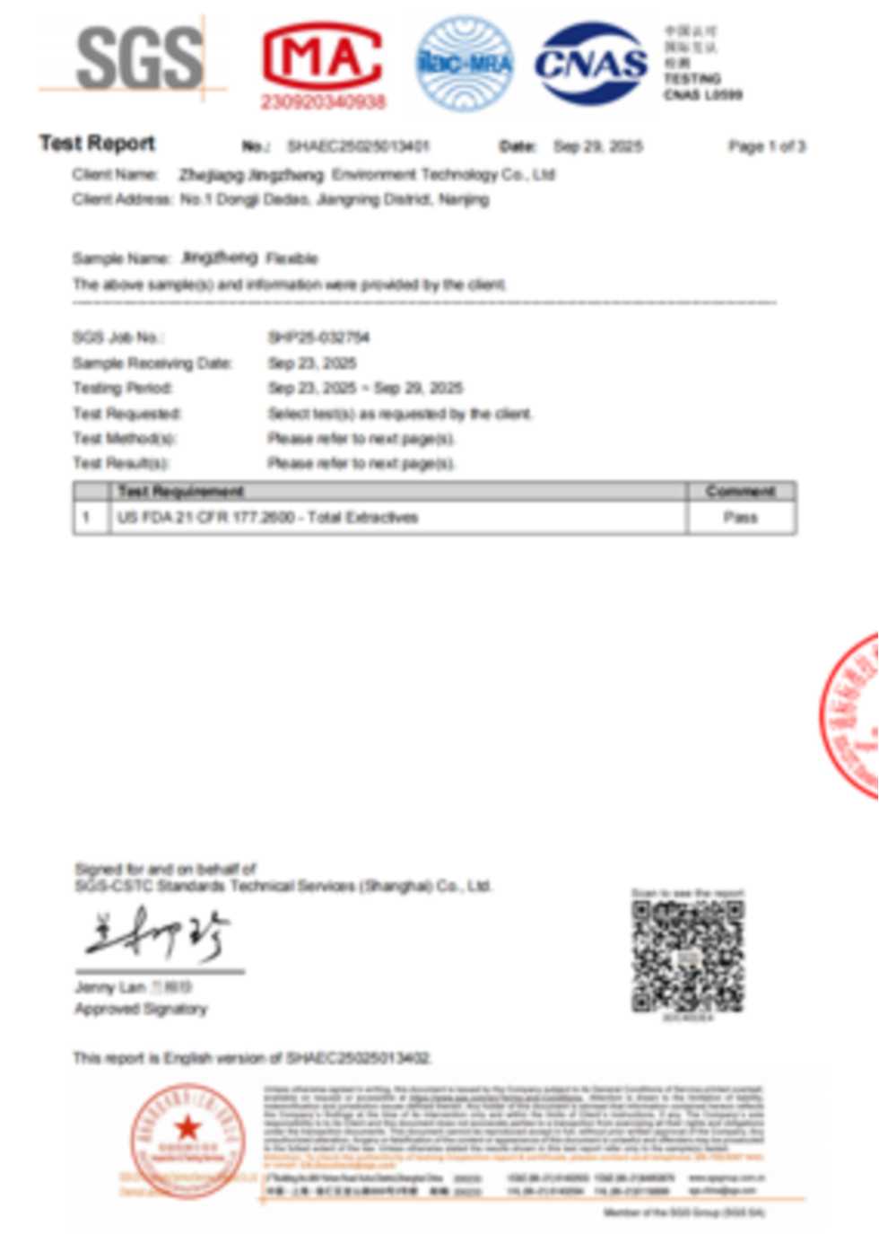
A: PU-10-VR can be specified with food-contact polyether TPU. SOSHH publishes FDA 21 CFR 177.2600 test documentation under Report TQT4821B36E for applicable polyether TPU configurations. Final food-contact suitability should be confirmed against the material grade, reinforcement construction, connector configuration and intended contact conditions before ordering.
Q6: How do I size a vacuum-reinforced flexible sleeve?
A:Specify the spigot seating diameter, installed face-to-face length, available installation gap, expected movement or stroke, vacuum and positive-pressure conditions, material or powder being conveyed, operating temperature, cleaning method and any food-contact or electrostatic requirements. See the How to Measure & Size a Snap-In Flexible Connector guide before final specification.
SOSHH How to Measure & Size
Q7: Is the polymer reinforcement located inside the product-contact bore?
A: No. The PU-10-VR uses non-metallic POM reinforcement rings housed in HF-welded pockets on the exterior of the sleeve. The reinforcement is outside the product-contact bore, so no metallic reinforcement is exposed within the product-contact path. The complete assembly may still contain stainless-steel spigots or other metal components.
For a broader comparison of connector interfaces, installation labor, changeover frequency and total cost of ownership, see our Flexible Connector Total Cost of Ownership Guide.