





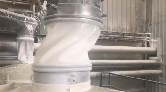
How to Choose an Abrasion-Resistant Flexible Connector
Selection Starts With the Operating Condition
An abrasion-resistant flexible connector is designed for powder and bulk-material handling applications where the connector must withstand both material contact and repeated mechanical movement.
The correct selection depends on the complete operating condition. Powder abrasiveness is important, but so are wall thickness, flexibility, installation gap, equipment stroke, temperature, pressure or vacuum, and the connection at each end.
For abrasive powder applications, SOSHH offers the PU-15 flexible connector with a 1.5 mm polyether TPU wall. The current product specification lists a DIN abrasion value of 39.0 mg, 40 MPa tensile strength, approximately 600% elongation at break, and a rated pressure range of +0.70 bar positive pressure and −120 mbar partial vacuum. Actual suitability depends on the final diameter, temperature, movement, and process conditions.
SOSHH PU-15 1.5 mm Flexible Connector for Abrasive Powders
Why Abrasion Resistance Matters in Flexible Connectors
A flexible connector is exposed to a different combination of loads from a rigid pipe.
The connector may need to:
- flex with vibrating equipment
- accommodate movement between two machine sections
- maintain the required process connection
- withstand contact with abrasive powders
- operate under positive pressure or vacuum
- remain suitable for the required cleaning and process temperature
In abrasive applications, wear usually becomes a maintenance problem before the rest of the equipment reaches the end of its service life.
The engineering objective is therefore not simply to make the connector thicker. The goal is to select a construction that provides sufficient wear resistance while retaining the flexibility required by the machine.
1. Start With the Powder Being Handled
The first specification question should be:
What material passes through the connector?
Abrasive applications can include minerals, metal powders, ceramic dust, resins, recycled materials, grains, crystalline powders, and other bulk solids.
The level of wear depends on more than the product name. Particle characteristics, conveying velocity, equipment movement, and the amount of contact with the connector wall also matter.
When requesting a quotation, provide the exact process material whenever possible.
Useful information includes:
- powder or bulk material
- particle characteristics
- abrasive duty
- conveying method
- operating temperature
- pressure or vacuum
- cleaning method
- whether the powder is combustible
2. Wall Thickness Creates More Wear Material
Wall thickness is one of the most direct design variables for abrasive service.
SOSHH currently lists PU-10 as a 1.0 mm polyether TPU construction and PU-15 as a 1.5 mm polyether TPU construction. The current PU-15 specification identifies the same general polyether TPU material family with a thicker wall for abrasive and high-velocity powder duty.
| FLEXIBLE CONNECTOR | WALL THICKNESS | TYPICAL DUTY |
|---|---|---|
| PU-10 | 1.0 mm | General powder, light and non-abrasive applications |
| PU-15 | 1.5 mm | Abrasive and high-velocity powder applications |
The important engineering difference is wall thickness rather than a change from TPU to a completely different polymer.
A thicker wall provides more material available before wear-through, but it can also affect flexibility. The final selection should therefore consider both wear and machine movement.
3. Verified PU-15 Technical Data
The following values are taken from the current SOSHH PU-15 product specification.
| PROPERTY | PU-15 VALUE |
|---|---|
| Material | 100% virgin polyether TPU |
| Wall thickness | 1.5 mm |
| Colour | Transparent |
| Abrasion (DIN) | 39.0 mg |
| Tensile strength | 40 MPa |
| Elongation at break | Approximately 600% |
| Temperature range | −30 °C to +85 °C continuous (short-term peak +110 °C; 85 °C CIP capable) |
| Standard surface resistivity | / |
| Static-dissipative option | 10⁶–10⁹ Ω/sq (IEC 60079-32-2 method) |
| Pressure rating | +0.70 bar / −120 mbar |
| Seam | / |
| Installation | Tool-free snap-in, 30–45 seconds per end |
| Food contact | FDA 21 CFR 177.2600, Report TQT4821B36 |
| EU formulation | EC 1935/2004 & EU 10/2011 |
| Standard size range | Ø102–804 mm × 100–1000 mm |
The published pressure figures are product specifications and should not be treated as a universal rating for every possible diameter, temperature, or installation. The current product page specifically notes that pressure performance is dependent on diameter and temperature.
SOSHH PU-15 Product Page
4. PU-15 and PU-20: When Is Heavy-Duty Construction Relevant?
SOSHH currently describes a heavy-duty PU-15 / PU-20 series using 1.5 mm and 2.0 mm monolithic polyether TPU constructions.
| HEAVY-DUTY GRADE | WALL | POSITIONING ON CURRENT SOSHH SITE |
|---|---|---|
| PU-15 | 1.5 mm | Abrasive and high-velocity powder processing |
| PU-20 | 2.0 mm | More demanding impact applications involving sharp, high-velocity aggregates |
The available information supports the use of PU-15 for abrasive powder service and PU-20 for more demanding impact conditions. A more detailed PU-20 pressure, abrasion, temperature, or tensile specification should only be published after Engineering verifies the corresponding datasheet.
SOSHH PU-15 & PU-20 Heavy-Duty Flexible Connectors
5. A Thicker Wall Does Not Mean “Maximum Flexibility”
Abrasion resistance and flexibility have to be considered together.
A flexible connector installed on a vibrating sifter, feeder, screener, or weighing system may experience repeated movement. If the connector is too stiff for the installation, the additional mechanical stress can shift to folds, clamps, cuffs, or connection areas.
The current PU-15 product specification reports approximately 600% elongation at break, indicating that the 1.5 mm construction remains a flexible TPU material rather than becoming a rigid component.
However, elongation at break is a material property, not a guarantee of a particular flex-cycle life.
Flex-cycle rating: /
Minimum bend radius:/
These values should be supplied before making a published lifetime or cycle-count claim.
6. Equipment Movement Must Be Included in the Specification
A connector on moving equipment should not be specified from diameter alone.
Before choosing the connector, measure:
- equipment connection diameter
- installed gap
- dynamic movement
- maximum extension
- maximum compression
- vibration conditions
- connection method at both ends
For snap-in installations, SOSHH’s sizing guide specifically asks engineers to consider spigot seating diameter, installation gap, dynamic stroke, media, temperature, and pressure.
How to Measure & Size a Snap-In Flexible Connector
For a vibrating sifter, the installed connector must have enough usable movement without bottoming out or being pulled excessively during operation.
Vibrating Sifter Flexible Connector
7. Abrasion Resistance in Pneumatic Conveying
Pneumatic conveying introduces additional loads because the connector may experience pressure, vacuum, and electrostatic effects.
The current SOSHH pneumatic conveying guide uses this decision framework:
| CONVEYING CONDITION | STARTING GRADE | CURRENT PUBLISHED SPECIFICATION |
|---|---|---|
| General powder, low pressure | PU-10 | 1.0 mm; +0.35 bar / −50 mbar |
| Abrasive / high-velocity powder | PU-15 | 1.5 mm; +0.70 bar / −120 mbar |
| Combustible dust | PU-10-AS | Static-dissipative 10⁶–10⁹ Ω/sq (IEC 60079-32-2 method); ATEX suitability must be evaluated against the site hazardous-area assessment |
| Full vacuum suction | PU-10-VR | −1000 mbar |
| High-pressure pulse / surge | PURF | Tensile strength / |
| High temperature up to 150 °C | PU-HT | −20 to +150 °C continuous |
This table is a selection framework rather than a statement that one connector can handle every load simultaneously.
For example, a line involving severe vacuum plus combustible dust may require a different engineering solution than an abrasive positive-pressure line.
Pneumatic Conveying Flexible Connector
8. What Can Cause an Abrasion-Resistant Connector to Fail?
Abrasion is only one possible failure mechanism.
| FAILURE MODE | DOMINANT CONDITION | ENGINEERING CONSIDERATION |
|---|---|---|
| Wall abrasion | High-velocity or abrasive powder | Consider PU-15 / heavier-duty construction |
| Ballooning | Positive pressure | Check pressure rating and reinforcement |
| Collapse | Vacuum | Check vacuum rating and reinforcement |
| Static accumulation | Combustible powder | Specify suitable dissipative configuration |
| Softening | High temperature | Select the correct temperature-rated material |
| Tear at connection | Excessive movement / poor installation | Check gap, stroke and connection geometry |
| Premature fold wear | Repeated vibration or incorrect geometry | Review dynamic movement |
| Chemical degradation | Aggressive cleaning or process media | Review material compatibility |
The final selection should identify the dominant load instead of assuming abrasion is the only design variable.
9. Abrasion-Resistant Material Selection
The SOSHH material guide currently places PU-15 within a broader material-selection system.
| MATERIAL / GRADE | WALL | TEMPERATURE RANGE | TYPICAL DUTY |
|---|---|---|---|
| PU-10 | 1.0 mm | −30 to +85 °C continuous (peak +110 °C) | General powder handling |
| PU-AS | 1.0 mm | −30 to +85 °C continuous (peak +110 °C) | Static-dissipative / combustible dust |
| PU-15 | 1.5 mm | −30 to +85 °C continuous (peak +110 °C) | Abrasive / high-velocity powder |
| PU-HT | 1.0 mm | −20 to +150 °C continuous | High-temperature transfer |
| PURF | Application-dependent | −30 to +85 °C continuous (peak +110 °C) | Pressure or vacuum reinforcement |
| PTFE | Machined | −70 to +260 °C (peak +280 °C) | Strong chemicals / extreme temperature |
| Silicone | 1.5 mm | −50 to +200 °C (121 °C SIP) | Hot air / drying applications |
The material should always be selected according to the complete process.
For example, a powder can be highly abrasive but also operate at a temperature beyond the normal TPU range. In that case, abrasion resistance alone is not sufficient to determine the correct material.
Flexible Connector Material Selection Guide
10. Connection Type Still Matters
An abrasion-resistant wall does not solve a connection problem.
SOSHH currently organizes flexible connector interfaces around snap-in, Tri-Clamp, LightTC, round flange, square/rectangular flange, and hose-clamp configurations.
| EQUIPMENT / SITUATION | STARTING INTERFACE |
|---|---|
| Frequent changeout on compatible spigot | SF Snap-In |
| Existing sanitary Tri-Clamp | TC Quick-Clamp |
| Weighing / gravimetric system | LightTC or suitable weighing configuration |
| Existing round flange | FLC Round Flange |
| Square / rectangular equipment | FLR Square Flange |
| Plain-pipe retrofit | HC Hose Clamp |
Connection choice should be based on equipment geometry, movement, cleaning, maintenance frequency, and process requirements.
Flange vs Clamp vs Snap-In Flexible Connector
11. Custom Abrasion-Resistant Connectors Are Not Limited to Equal-Diameter Ends
A common engineering requirement is for the two ends of a flexible connector to have different dimensions.
Actual RFQ records supplied for this project include requests such as:
- “Can the diameter and length be customized?”
- “Can you make a reducer — different diameter at each end?”
- “Can one end be internal snap-in and the other end a clamp?”
- “Can a quick-release connector be made square or rectangular?”
- “How tall can a flexible connector be?”
These are not theoretical SEO questions; they were recorded as actual RFQ questions in the supplied engineering data.
Different Diameters
A reducer connector can be specified with a different diameter at each end.
Example:
Top: Ø89 mm
Bottom: Ø159 mm
The exact geometry should be confirmed from the equipment drawing or measured dimensions.
Round-to-Square Transitions
A circular sifter or pipe may need to connect to a square or rectangular hopper.
In this case, provide the round-end diameter and the square or rectangular end dimensions.
Mixed Connections
One end can require a snap-in interface while the other uses a clamp or flange.
This is especially useful for retrofit installations where the two existing machines have different connection architectures.
Variable Height
For installations with changing separation between two machine sections, provide the required installed, extended, and compressed dimensions.
Where a specific compression ratio is required:
Extended length:/
Compressed length:/
Do not publish a generic compression ratio unless the relevant connector construction has been verified.
12. Real RFQ Questions From SOSHH Engineering Records
The following questions are based on the actual RFQ questions in the supplied SOSHH engineering material. They have been translated and lightly edited into natural technical English while preserving the original intent.
Q1. Can the diameter and length of a flexible connector be customized?
Yes. SOSHH supports custom dimensions for flexible connectors. Provide the required diameter, installation gap, connection type, and material/process conditions for engineering review.
Q2. Can you make a reducer with a different diameter at each end?
Yes. Custom reducer configurations can be specified where the two equipment connection points have different diameters.
For example, an application may require Ø89 mm at one end and Ø159 mm at the other.
Q3. Can one end be internal snap-in and the other end a clamp or flange?
Yes. Mixed-end connection configurations can be specified for retrofit installations and equipment with different interface types.
Q4. Can a quick-release flexible connector be made square or rectangular?
Yes. SOSHH has square and rectangular flexible connector configurations. The final dimensions and connection geometry should be provided for engineering review.
Q5. How tall can a flexible connector be?
The required height is application-dependent. Standard size information is available for current product families, while non-standard dimensions can be reviewed as custom requirements.
For moving equipment, provide both the installed condition and the required extension/compression.
Q6. What is the temperature rating?
For the current PU-15 product, the temperature range is −30 °C to +85 °C continuous (short-term peak +110 °C; 85 °C CIP capable).
For applications above the PU-15 temperature range, another material grade may be required. SOSHH currently lists PU-HT for applications up to +150 °C and PTFE for substantially higher temperature or aggressive chemical requirements.
Q7. Do I need a separate sealing gasket?
For the snap-in architecture, the connector is designed around its connection interface rather than relying on a separate loose gasket. The exact gasket requirement depends on the final connector configuration and equipment interface.
Q8. Is an anti-static version available?
Yes. SOSHH currently lists static-dissipative TPU configurations with a published surface-resistance range of 10⁶–10⁹ Ω/sq (IEC 60079-32-2 method) for appropriate combustible-dust applications.
ATEX suitability should be evaluated against the complete installed system and hazardous-area requirements.
Anti-Static Flexible Connector Guide
Q9. How do I get a price?
Provide the connector dimensions, installation gap, connection types, material, operating conditions, and quantity.
For non-standard connectors, a drawing or clear photograph of the existing installation can significantly improve the quotation review.
Q10. What drawing files can I get before ordering?
For custom engineering work, drawing availability depends on the project and confidentiality requirements.
Current SOSHH engineering materials distinguish between evaluation drawings and detailed CAD files. Confirm the available drawing format and any NDA or NNN requirement with the engineering team.
13. PU-15 Product FAQ Based on Current SOSHH Product Information
Is PU-15 a different material from PU-10?
No. The current SOSHH product information identifies both PU-10 and PU-15 as polyether TPU constructions. The principal difference is wall thickness: PU-10 is 1.0 mm while PU-15 is 1.5 mm.
Does the thicker wall reduce flexibility?
The current PU-15 specification reports approximately 600% elongation at break. SOSHH positions PU-15 as a flexible construction suitable for vibration and offset while providing a larger wear reserve.
Actual movement suitability still depends on connector geometry and installation.
What pressure can PU-15 handle?
The current published PU-15 rating is:
Positive pressure: +0.70 bar
Vacuum: −120 mbar
The product page notes that the pressure rating depends on diameter and temperature.
Is PU-15 food-contact compliant?
The current PU-15 product page lists FDA 21 CFR 177.2600 compliance with report reference TQT4821B36 and also lists EC 1935/2004 and EU 10/2011 formulation.
Food-contact compliance should always be checked against the exact material and final configuration being purchased.
Does PU-15 put metal into the product stream?
The current product information describes the snap-in retention system as integrated into the connector construction rather than exposed in the powder-contact bore.
For metal-detection-sensitive applications, evaluate the complete installed assembly and the exact connector configuration.
How do I size a PU-15?
Measure:
- Spigot seating OD
- Installation gap
- Dynamic stroke
- Process media
- Temperature
- Pressure or vacuum
A drawing or clear installation photograph can also be supplied for engineering review.
What is a 1.5 mm polyurethane flexible connector used for?
PU-15 is intended for powder-handling applications involving abrasive media and high-velocity powder. The thicker wall provides additional material before wear-through compared with a 1.0 mm construction.
What is the difference between a 1.0 mm and 1.5 mm flexible connector?
The principal difference is wall thickness.
PU-10: 1.0 mm
PU-15: 1.5 mm
Both use polyether TPU in the current SOSHH product range. The 1.5 mm construction provides more wear material for abrasive service.
14. What Information Should You Send for an Abrasion-Resistant Connector Quote?
A useful RFQ should contain the following engineering information.
| ENGINEERING INPUT | WHAT TO PROVIDE |
|---|---|
| Equipment | Sifter, screener, feeder, hopper, conveyor, rotary valve, etc. |
| Process material | Exact powder or bulk material |
| Abrasion duty | Low / moderate / high or existing wear problem |
| Diameter | Both ends |
| Installation gap | Installed distance between connection points |
| Movement | Stroke, vibration or axial movement |
| Connection | Snap-in, flange, Tri-Clamp, clamp, mixed |
| Temperature | Normal and maximum |
| Pressure | Positive pressure if applicable |
| Vacuum | Negative pressure if applicable |
| Static | Combustible dust / anti-static requirement |
| Quantity | Required quantity |
| Drawing | Dimensioned drawing, DWG, STEP, PDF, or photograph |
SOSHH’s current pneumatic-conveying guidance similarly asks for the line spigot OD, installed gap, conveying mode, operating pressure, operating vacuum, powder type and abrasiveness, temperature, and static requirement.
15. What Should Not Be Estimated?
For engineering products, unsupported performance numbers can be worse than leaving a field blank.
The following should only be published when backed by current product-specific documentation:
| PERFORMANCE CLAIM | STATUS |
|---|---|
| DIN abrasion value for PU-15 | Verified: 39.0 mg |
| Tensile strength for PU-15 | Verified: 40 MPa |
| Elongation at break for PU-15 | Verified: approximately 600% |
| PU-15 temperature range | Verified: −30 to +85 °C continuous (peak +110 °C; 85 °C CIP) |
| PU-15 pressure rating | Verified: +0.70 bar / −120 mbar |
| PU-15 standard size range | Verified: Ø102–804 mm × 100–1000 mm |
| Generic connector service life | / |
| Generic abrasion life in months/years | / |
| Flex-cycle count | / |
| Maximum conveying velocity | / |
| Maximum particle size | / |
| Minimum bend radius | / |
| Generic wear-through time | / |
This distinction keeps the article technically useful without turning laboratory or product-specific figures into universal guarantees.
16. Abrasion-Resistant Flexible Connector Selection Checklist
Before ordering, confirm these questions:
Material: What is being conveyed?
Wear: Is the application abrasive or high velocity?
Wall: Is the standard construction sufficient, or should a thicker wall be considered?
Movement: How much does the equipment move?
Gap: What is the actual installation gap?
Temperature: What are the normal and maximum temperatures?
Pressure: Is the application under positive pressure?
Vacuum: Is negative pressure present?
Static: Is the powder combustible?
Connection: What is required at each end?
Geometry: Are the diameters equal, reduced, offset, round-to-square, or mixed?
Maintenance: How frequently is the connector inspected or replaced?
17. When to Consider SOSHH PU-15
PU-15 is a logical starting point when the application involves abrasive or high-velocity powder and the process remains within the published PU-15 operating envelope.
The current SOSHH product information specifically identifies PU-15 for:
- abrasive powder
- minerals
- metal powders
- ceramics
- resins
- high-velocity pneumatic conveying
- applications where a standard sleeve is wearing through too quickly
For applications combining severe abrasion with deep vacuum, high pressure pulses, high temperature, combustible dust, or aggressive chemicals, do not select the connector from abrasion resistance alone. Use the complete operating condition to determine the required construction.
Request an Abrasion-Resistant Flexible Connector
Need an abrasion-resistant flexible connector for an existing powder-handling system?
Send:
- connector diameter
- installation gap
- connection type
- powder/material
- temperature
- pressure or vacuum
- equipment movement
- quantity
- drawing or photograph
SOSHH can review the installation and determine whether PU-15, another standard grade, or a custom construction is appropriate.
Request a Custom Flexible Connector Quote
For applications with non-standard diameters, reducers, square-to-round transitions, mixed connection ends, or custom heights:
SOSHH Custom Non-Standard Flexible Connectors