


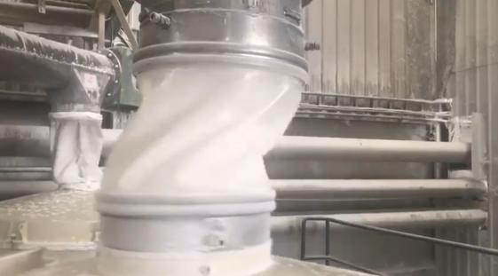
How to Measure & Size a Snap-In Flexible Connector: Dynamic Movement and Installation Guide
Measure the Equipment Interface, Not the Old Connector
A flexible connector should always be measured from the equipment interface, never from the existing sleeve.
A used connector may already be stretched, compressed, heat-aged, chemically exposed, or permanently deformed during operation. Using it as the sizing reference can create incorrect length and diameter assumptions, resulting in installation tension, poor sealing, excessive cuff stress, and premature fatigue failure.
For accurate snap-in flexible connector selection, measure:
- Actual spigot outside diameter (OD)
- Groove depth and retention geometry
- Lip profile and edge radius
- Installed face-to-face gap
- Both end connection dimensions
- Operating movement conditions
For vibrating powder equipment, connector sizing must follow the complete movement envelope — not only the static installation gap.
Why Measuring the Existing Sleeve Creates Sizing Errors
Replacement failures often begin during measurement.
Many users copy the dimensions of a failed connector or select a replacement based only on nominal pipe size. This approach ignores the actual equipment geometry and operating movement.
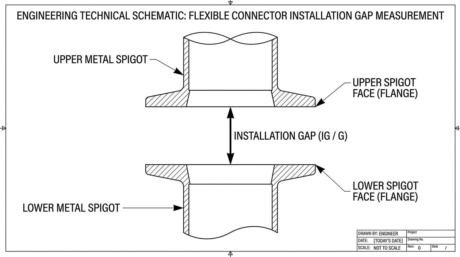
Figure 1:Determine the true installation gap (G) between rigid metal spigots at rest.
| Incorrect Reference | Engineering Result |
|---|---|
| Old stretched sleeve | Incorrect length measurement |
| Heat-aged connector | False diameter reference |
| Nominal pipe size | Incorrect spigot fit |
| Static gap only | Connector fatigue during operation |
A flexible connector is a dynamic component. Correct sizing requires understanding how the connector moves during operation, not only how it looks when equipment is stopped.
Measure the Metal Interface, Not the Old Sleeve
The metal connection points define the true connector dimensions.
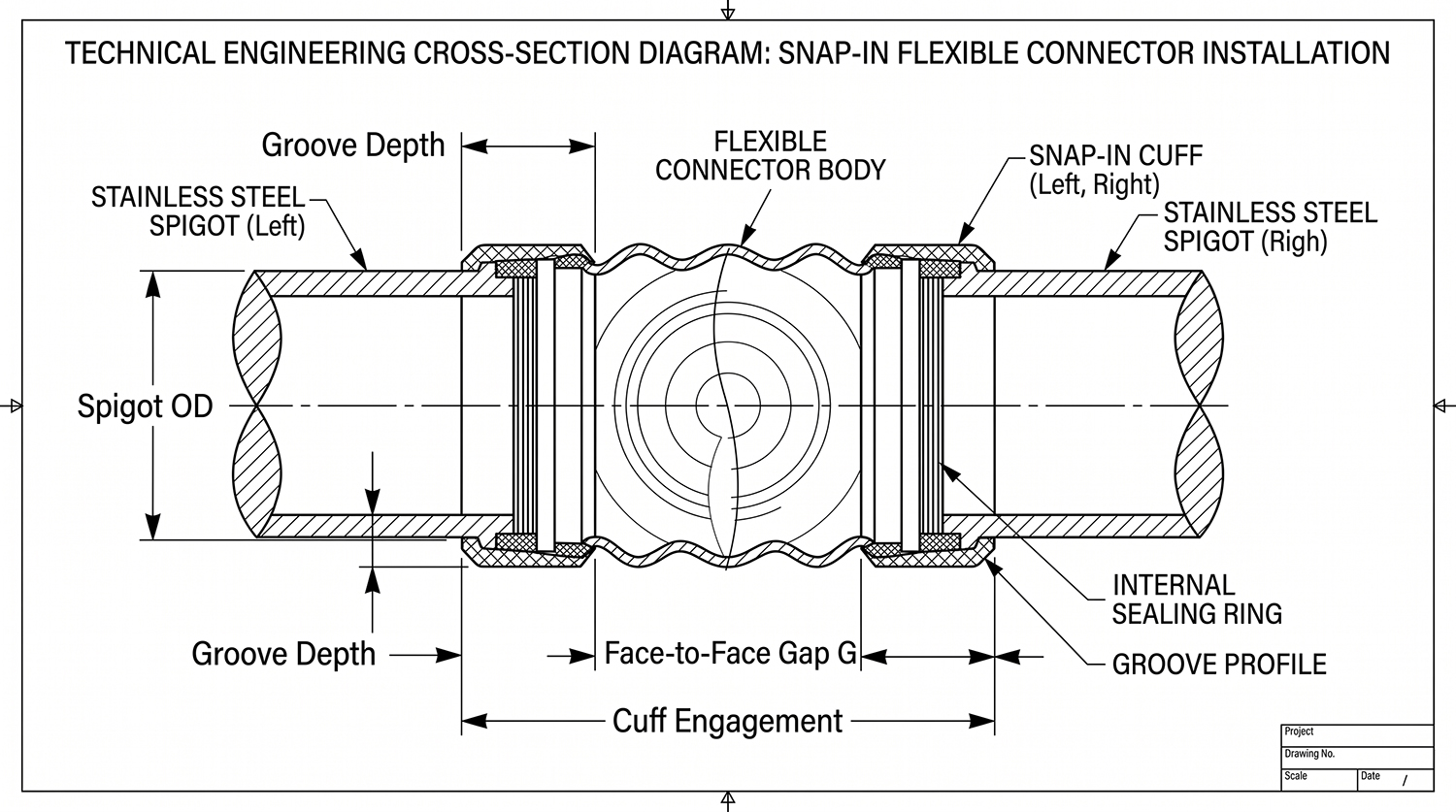
Figure 2: Measurement reference points for snap-in flexible sleeves. Always measure spigot OD, groove depth, lip radius, and face-to-face gap directly from the precision metal interfaces.
| Measurement Point | Engineering Purpose |
|---|---|
| Spigot outside diameter (OD) at both ends | Defines the actual seating diameter |
| Groove depth and geometry | Determines cuff engagement and retention |
| Lip profile and edge radius | Influences sealing contact and installation |
| Face-to-face installation gap | Defines the neutral connector length |
| Both end connection types | Prevents incorrect asymmetric design |
Both ends must be measured separately because industrial equipment often contains different connection geometries.
Do not rely on:
- Previous connector dimensions
- Catalog diameter only
- Nominal pipe size
Measure the actual installed equipment.
Dynamic Length Calculation for Vibrating Applications
A flexible connector must not be designed equal to the static installation gap.
During operation, the connector must absorb:
- Axial movement
- Compression
- Lateral offset
- Equipment vibration
- Installation sag
The minimum natural (relaxed) connector length before installation:
L0 ≥ G + 2 × S_sag + ΔA_stroke + ΔR_offset + C_cuff
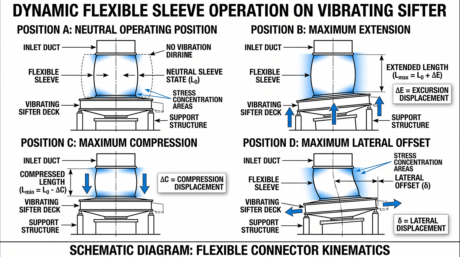
Figure3: Four-position operating verification envelope (Neutral, Max Extension, Max Compression, and Lateral Offset) ensuring stress-free dynamic operation.
| Variable | Engineering Meaning |
|---|---|
| L0 | Minimum natural connector length before installation |
| G | Static net gap between defined metal reference faces |
| S_sag | Sag allowance preventing excessive tension or uncontrolled folding |
| ΔA_stroke | Axial or vertical movement allowance |
| ΔR_offset | Maximum lateral displacement allowance |
| C_cuff | Combined engagement depth of both cuffs |
The 2 × S_sag allowance is critical.
A connector sized exactly to the static gap operates under continuous tension during vibration. This increases stress concentration at:
- Cuffs
- Welded transitions
- High-flex areas
The final connector length should always be verified against:
- Equipment movement
- Temperature changes
- Cleaning procedures
- Installation conditions
Four-Position Dynamic Fit Verification
A correctly sized flexible connector must pass all operating positions.
| Operating Position | Engineering Verification |
|---|---|
| Neutral position | Connector remains flexible without excessive tension or uncontrolled folding |
| Maximum extension | No pulling force on cuffs or welded areas |
| Maximum compression | No crushing, pinching, or powder blockage |
| Maximum lateral offset | No twisting, seal failure, or uneven loading |
If a connector only fits the neutral position, it is under-designed for dynamic operation.
Snap-In Flexible Connector Sizing Checklist
Before requesting a replacement connector, collect the following information:
| Required Information | Engineering Requirement |
|---|---|
| Equipment type | Sifter, feeder, hopper, rotary valve, or powder equipment |
| Spigot OD at both ends | Actual measured dimensions |
| Groove geometry | Depth, width, retention profile |
| Installation gap | Face-to-face measurement |
| Movement conditions | Frequency, amplitude, lateral displacement |
| Temperature conditions | Operating and cleaning temperatures |
Complete measurement data allows correct selection of:
- Connector length
- TPU material grade
- Wall thickness
- Reinforcement structure
- End connection design
Common Measurement Mistakes and Their Consequences
| Measurement Mistake | Consequence |
|---|---|
| Measuring the old sleeve | Incorrect length and diameter reference |
| Using nominal pipe size | Poor connector fit |
| Sizing only to static gap | Excessive vibration stress |
| Ignoring lateral movement | Cuff twisting and seal failure |
| Ignoring cuff engagement depth | Connector slipping or poor retention |

Figure 4: Failure analysis — tension cracking caused by short sleeves vs. S-folding abrasion caused by excess length.
Engineering Example: Correcting a Failed Vibrating Sifter Connector Replacement
A customer replaced a vibrating sifter flexible connector using the old sleeve dimensions.
The replacement failed because the original connector had already stretched during service and the installation gap was measured incorrectly.
| Previous Method | Engineering Solution |
|---|---|
| Measured old connector | Measured actual metal spigots |
| Used static gap only | Calculated complete movement envelope |
| Standard replacement length | Customized connector geometry |
Result:
- Improved sealing performance
- Reduced cuff stress
- Better vibration compensation
- Extended connector service life
FAQ — Snap-In Flexible Connector Measurement and Sizing
| Question | Answer |
|---|---|
| Why should I avoid measuring the old connector? | Old connectors are stretched, worn, and heat-aged, creating inaccurate dimensions. |
| Is nominal pipe diameter enough for selection? | No. Actual spigot OD and groove geometry are required. |
| Do vibrating connectors require movement calculations? | Yes. Connector size must consider extension, compression, and lateral offset. |
| Why does a replacement connector fail quickly? | Common causes include incorrect measurement, insufficient movement allowance, and wrong geometry. |
| Can SOSHH help select the correct connector size? | Yes. Send equipment photos, dimensions, and operating conditions for engineering review. |
Engineering Support from SOSHH
Sizing errors usually come from measuring the wrong reference or ignoring the actual movement envelope.
Send your application details and SOSHH engineering team will recommend the correct connector design.
Please provide:
- Equipment and existing connector photos (front and side view)
- Spigot OD measurements at both ends and groove geometry
- Installed face-to-face gap
- Vibration frequency and movement amplitude
- Powder type and operating temperature
You will receive:
- Technical material and TPU grade recommendation
- Connector length and geometry selection
- Customized drawing support
- Prototype and sample development
- Fast engineering response for urgent projects
For qualified projects:
Same-day technical review → Same-day drawing preparation → Same-day sample shipment
Submit Your Application Details
Email: amin@soshh.com