





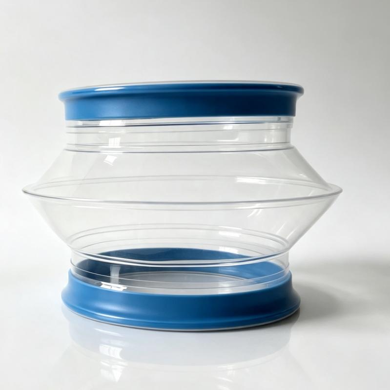
How a Flexible Connector Affects Loss-in-Weight Feeder Accuracy
For an LIW feeder, the flexible connector is part of the mechanical measurement path. Its job is to contain the process while allowing the weighed assembly to move with minimal additional reaction force.
The goal is not “zero force.” The practical engineering goal is low and predictable reaction force within the required operating envelope.
The Problem: A Flexible Connector Can Become a Spring
Every flexible connector has some stiffness. A simplified way to visualize the effect is:
Reaction force ≈ stiffness × displacement
This is a conceptual relationship rather than a connector rating. Real elastomeric bellows are nonlinear, and their behavior depends on material, wall thickness, convolution geometry, length, temperature and direction of movement. But the principle is useful: the more strongly the connector resists movement, the more mechanical force it can feed back into the weighing system.
In an LIW feeder, the hopper or feeder body may move slightly as material is discharged, refilled, vibrated, or thermally cycled. If a connected hose or sleeve resists that movement, the load cells may see an additional force. That can appear as baseline movement, tare drift, weight fluctuations, poor repeatability, different zero points at different temperatures, apparent calibration instability, and feed-rate variation during process-pressure changes.
1. What Makes a Connector Suitable for Weighing?
A weighing connector should satisfy several requirements simultaneously:
- Low mechanical reaction force — accommodate expected movement without creating unnecessary axial, lateral or angular resistance.
- Stable geometry — remain in a controlled operating shape instead of being pulled tight, folded against itself, or allowed to sag unpredictably.
- Reliable containment — contain powder and process air under the actual pressure, vacuum and cleaning conditions.
- Appropriate flexibility — a connector that is extremely soft is not automatically correct. Excessive softness can create instability, sagging, abrasion or collapse under pressure/vacuum.
- Correct connection method — match the equipment interface without creating a rigid mechanical bridge.
- Suitable material — survive process temperature, cleaning cycle, powder characteristics, chemical environment and static requirements.
The engineering target is therefore: low reaction force + adequate containment + controlled movement + suitable environmental resistance.
2. Why Wall Thickness Matters
Wall thickness has a direct influence on flexibility. For a weighing application, a thinner flexible section reduces the force required to deform the connector. LIW installation guidance has long recommended using the thinnest practical connecting material, forming a bellows, maintaining alignment and avoiding installation under tension.
That does not mean “the thinnest possible wall is always best.” A thinner wall can reduce abrasion resistance, tear resistance, pressure stability, vacuum resistance and mechanical robustness. The actual question is:
What is the minimum structural thickness that provides the required service life without unnecessarily increasing mechanical stiffness?
SOSHH’s weighing products reflect this trade-off through different constructions. The current HC silicone weighing connector uses a thin 0.8–1.0 mm belly with reinforced 2.0 mm cuffs, while the SF-WeighFlex product uses a dedicated multi-convolution TPU architecture for weighing applications.
3. Bellows Geometry Is More Important Than a Generic “Soft Hose”
A weighing connector should not be selected simply because its material feels soft. Geometry controls how the connector responds when the equipment moves. A bellows or multi-convolution design accommodates movement through controlled deformation rather than forcing the entire wall to stretch in one direction.
For LIW installations, the practical design objectives are: allow vertical movement, allow expected lateral movement, accommodate thermal expansion, avoid hard contact between turns, avoid excessive compression, avoid full extension, avoid twisting, avoid contact with neighboring structures, and avoid transferring downstream vibration into the weighing assembly.
A properly designed bellows behaves like a controlled mechanical interface. A badly installed bellows can behave like a spring, restraint or rigid link.
4. Installation Geometry Can Make a Good Connector Behave Badly
Even an appropriate connector can cause weighing problems when installed incorrectly. LIW installation guidance specifically recommends thin flexible material, a bellows shape that allows expansion and contraction, aligned connections, adequate clearance, and no stretching during tightening.
Do not install the connector under tension. If the connector is stretched before the clamps are secured, it is already applying force to the equipment. The weighing system may start with an artificial mechanical load.
Do not force an offset. A connector should not be used to correct a major misalignment that should have been solved by the equipment geometry.
Do not let the connector become a structural support. It should connect equipment — not carry the weight of downstream piping, electrical conduit, valves, ducting or other equipment. Attached piping can transmit forces to a weighed vessel as the vessel and structure deflect; the issue becomes more significant as the weighed capacity becomes smaller relative to the forces imposed by connected piping.
5. Net Gap: The Dimension Engineers Should Not Guess
Measure the distance between the two connection surfaces with the equipment in its normal neutral position. For moving equipment, also consider minimum and maximum operating gap, vertical stroke, lateral displacement, angular movement, vibration amplitude and thermal expansion.
A connector that is too short can become tensioned. A connector that is too long can sag, fold unpredictably or add an uncontrolled mechanical influence. The objective is not merely to “make it fit” — it is to define an installed geometry in which the connector can move through its operating range without becoming a significant mechanical restraint.
How to Measure & Size
6. The Connector Is Not the Only Force Path
When an LIW feeder drifts, do not automatically replace the connector or recalibrate the load cell. The weighing assembly can be affected by several mechanical and process influences:
- Rigid inlet or discharge piping
- Heavy downstream valves
- Unsupported ducting
- Cable or conduit restraints
- Pipe thermal expansion
- Structural deflection
- Mechanical stops
- Vibration transfer
- Hopper contact with surrounding equipment
- Incorrect mounting
- Material buildup
- Process-pressure fluctuations
- Inadequate hopper venting
A flexible connector is one part of a mechanically isolated weighing system — not the whole system.
7. Pressure Can Create a False Weight Signal
An LIW feeder can experience pressure changes during material refill, discharge into a pressurized process, vacuum conveying, pneumatic transfer, nitrogen blanketing, dust-collection operation, vent-filter loading or blockage, and valve switching. Even a relatively small pressure differential can generate a force on the weighing assembly.
This creates two different engineering problems that can occur at the same time:
Mechanical interference — the connector transmits force because it resists movement.
Pressure interference — the process changes the force acting on the weighed assembly because pressure changes.
That is why an RFQ should never say only “loss-in-weight feeder connector.” It should also specify the pressure or vacuum condition.
8. Check the Hopper Vent as Well
The weighing connector may be correctly selected while the venting system creates the actual disturbance. During refill, incoming material displaces air. If the hopper vent is restrictive, pressure can temporarily build up. Potential causes include an undersized vent, a loaded filter, a blocked vent, dust-collector suction changes, incorrect vent configuration, or nitrogen/purge-gas pressure.
When diagnosing tare drift or post-refill disturbances, inspect both the flexible connector and the hopper pressure-management system.
9. Choosing the Right SOSHH Weighing Connector
The selection should be driven by the complete process envelope rather than by the temperature rating alone.
| APPLICATION CONDITION | STARTING CONFIGURATION | WHY |
|---|---|---|
| General LIW / gravimetric weighing | SF-WeighFlex TPU | Dedicated multi-convolution weighing geometry and flexible snap-in architecture |
| Non-abrasive food/pharma powder | HC Silicone Weighing Connector | Thin flexible belly with reinforced cuffs; designed for weighing duty |
| Higher-temperature hot-air / drying duty | Platinum-cured silicone | Broad published temperature range with high flexibility |
| Abrasive powder | TPU construction selected for abrasion duty | Better wear resistance than a very soft silicone construction |
| Static-sensitive powder | Static-dissipative TPU grade | Controlled charge dissipation while maintaining flexible architecture |
| Aggressive chemical + high-temperature duty | PTFE weighing bellows | Strong chemical resistance and high-temperature capability |
| Vacuum-sensitive LIW application | Vacuum-rated / reinforced construction | Designed around collapse resistance rather than flexibility alone |
These are starting points, not automatic approvals. The final selection depends on material, wall construction, geometry, diameter, installed gap, pressure/vacuum, temperature, movement and cleaning cycle.
10. SF-WeighFlex TPU for General Gravimetric Applications
The current SF-WeighFlex is a dedicated multi-convolution TPU weighing bellows for loss-in-weight feeders, with an ultra-flexible polyether TPU construction, a 70 Shore A formulation, a 0.8–1.0 mm flexible belly, multi-convolution geometry, tool-free snap-in cuffs, and food-contact documentation associated with the configuration.
SF-WeighFlex TPU Weighing Bellows
11. HC Silicone Weighing Connector
The HC Series Silicone Weighing Flexible Connector is positioned for loss-in-weight feeders, load-cell hoppers, micro-dosing scales, gravimetric dosing and sanitary powder handling. It uses a 0.8–1.0 mm flexible belly with 2.0 mm reinforced straight cuffs to balance flexibility in the working section with clamp-retention strength at the ends. The silicone construction is published at −50 °C to +200 °C and is suitable for CIP-oriented applications.
HC Silicone Weighing Connector
12. Silicone: High Temperature Does Not Automatically Mean SIP
A material can have a high continuous temperature range without having a validated repeated steam-sterilization cycle. For a SIP requirement, specify steam temperature, steam pressure, cycle duration, number of cycles, cooling cycle, chemical exposure before or after SIP, and whether the connector remains installed during sterilization.
SOSHH’s material guide lists its virgin PTFE bellows as compatible with 121 °C live-steam SIP. It does not follow that every silicone connector with a +200 °C temperature rating carries the same validated SIP claim. Treat SIP as a separate qualification requirement, not a simple consequence of the temperature rating.
13. When to Consider PTFE
PTFE becomes more relevant when weighing duty is combined with aggressive chemicals, solvent exposure, high temperature, repeated sterilization, demanding vacuum conditions, or difficult process environments.
SOSHH’s material guide lists virgin PTFE bellows at −70 °C to +260 °C and identifies 121 °C live-steam SIP compatibility. However, the SF-VacuScale PTFE weighing product is a specific construction with its own published performance envelope — a PTFE-fabric bellows with a listed thermal range of −60 °C to +220 °C and vacuum-oriented reinforcement.
This distinction is important: do not use a general material temperature limit as though it were the guaranteed rating of every finished PTFE connector. Select the exact product construction against the actual pressure, vacuum, movement and thermal cycle.
SF-VacuScale PTFE
14. Abrasion Can Reverse the Material Decision
The softest connector is not necessarily the longest-lasting connector. A very abrasive powder can wear a thin, highly compliant wall much faster than a thicker abrasion-oriented construction — mineral powders, ceramic powders, glass powder, some crystalline ingredients, highly loaded compounds, and high-velocity solids.
The correct solution may require a controlled compromise: slightly more wall thickness for service life, while preserving enough flexibility for the weighing system. For an abrasive LIW application, provide the powder name and conveying velocity rather than simply stating “abrasive.”
15. Static Dissipation for Combustible Powders
Some powders accumulate electrostatic charge during transfer and mixing. Dry powders can build static electricity during frictional transfer and mixing, and require appropriate grounding and bonding precautions where combustible-dust hazards are present.
SOSHH lists a static-dissipative TPU grade, PUAS, with a published surface-resistance range of 10⁶–10⁹ Ω/sq tested to IEC 60079-32-2, positioned for combustible-dust areas and fine organic powders. For an RFQ, specify whether the powder is combustible, the applicable hazardous-area classification, the required surface-resistance range, the grounding/bonding arrangement, and any plant or customer standard. A dissipative connector is part of the control strategy; it does not replace correct system grounding and bonding. ATEX suitability must be evaluated against the site hazardous-area assessment.
16. Food and Pharmaceutical Weighing: Separate Hygiene From Mechanics
A connector can be mechanically excellent and still be unsuitable for a sanitary process. For food and pharmaceutical applications, evaluate product-contact material, surface finish, internal product traps, crevices, cleaning method, cleaning chemistry, cleaning temperature, sterilization method, required documentation and traceability.
The silicone weighing connector uses a smooth internal wall and is positioned for CIP-oriented powder applications. For regulatory documentation, ask for the exact material and finished-product documentation applicable to the ordered configuration. Do not rely on the phrase “food grade” without identifying the relevant material and test documentation.
17. Why Heavy-Duty Connectors Can Be Wrong for Weighing
A common instinct is “more material means more durability.” That can be correct for abrasion and wrong for weighing. A heavy connector may introduce higher axial and lateral stiffness, greater restoring force, more reaction to thermal movement, more vibration coupling, more weight, and more mechanical influence on the load-cell assembly.
The correct design is not maximum wall thickness. It is minimum practical mechanical stiffness consistent with the required service life.
18. Common Weighing-System Failure Modes
| SYMPTOM | POSSIBLE MECHANICAL CAUSE | WHAT TO INSPECT |
|---|---|---|
| Baseline drift | Connector under tension or excessive stiffness | Installed gap, wall construction, connector shape |
| Different zero at different temperatures | Thermal expansion restraint | Connector and attached piping |
| Weight fluctuates with vibration | External vibration transferred into weighing structure | Downstream support and connector stiffness |
| Disturbance after refill | Hopper pressure or venting issue | Vent, filter, refill sequence |
| Reading changes when downstream equipment starts | Mechanical or pressure coupling | Discharge connector, ducting, downstream pressure |
| Recalibration seems frequent | External force path not controlled | Piping, cables, valves, contact points |
| Connector wears quickly | Material too soft for powder abrasion | Powder characteristics, velocity, wall thickness |
| Connector collapses under vacuum | Construction not vacuum-rated | Reinforcement and operating vacuum |
| Connector tears at clamp | Flexible belly too close to clamp load | Cuff reinforcement and clamp installation |
| Signal changes when hose is repositioned | Mechanical force path changes | Hose length, sag, alignment and installed tension |
19. A Five-Minute Mechanical Audit
Before replacing a load cell or recalibrating the feeder, inspect the complete force path:
- Connector tension — is the connector stretched at the neutral position?
- Alignment — are the connection centers aligned?
- Installed gap — does the connector have enough working length for the actual movement?
- Downstream support — is any rigid pipe, valve or duct hanging from the weighed equipment?
- Cable and conduit — can electrical wiring or tubing pull against the hopper as it moves?
- Contact points — does the hopper touch surrounding frames, guards or piping?
- Pressure — does process pressure change during refill or discharge?
- Venting — can displaced air leave the hopper without creating transient pressure?
- Powder buildup — is material accumulating around the connector and changing its mass or stiffness?
- Dynamic movement — does the connector remain stable through the complete vibration and operating cycle?
20. How to Choose the Connection Type
Material and connection interface should be selected independently. Possible interfaces include snap-in, quick-clamp/Tri-Clamp, hose clamp, round flange, square or rectangular flange, and custom mixed-end connection. The correct interface depends on equipment geometry, sanitation requirements, maintenance frequency and available installation space.
For weighing applications, also consider the mass and mechanical stiffness of the connection hardware. A lightweight connection can be advantageous, but the priority remains stable containment with minimal unintended mechanical coupling.
Flange vs Clamp vs Snap-In TCO
21. What to Send SOSHH for a Weighing Connector Quote
Application: system type, exact powder or bulk solid, bulk density, particle characteristics.
Dimensions: top/bottom connection OD, connection ID, installed neutral gap, minimum and maximum gap, connector length available.
Movement: vertical movement, horizontal movement, angular movement, vibration amplitude, vibration frequency.
Process: normal and maximum temperature, cleaning method, cleaning temperature, cleaning chemicals.
Pressure: positive pressure, vacuum, pressure fluctuations, downstream equipment.
Compliance: food contact, pharmaceutical, static dissipative, hazardous-area classification, required documentation.
Commercial: quantity, new or replacement, drawing available, photo available.
22. Weighing Connector Selection: Quick Decision Guide
General ambient-temperature LIW — start with a dedicated low-reaction-force TPU weighing construction. SF-WeighFlex TPU
Food or pharmaceutical powder with high flexibility requirements — evaluate platinum-cured silicone weighing construction where abrasion is relatively low. HC Silicone Weighing Connector
Hot-air or drying application — evaluate a high-temperature silicone construction against the complete pressure, movement and cleaning envelope.
Abrasive powder — evaluate a more abrasion-resistant TPU construction rather than automatically choosing the softest possible wall.
Combustible or static-sensitive powder — evaluate a static-dissipative grade and the complete plant grounding/bonding arrangement. Material Selection Guide
Chemical + high temperature — evaluate PTFE.
Vacuum + weighing — use a vacuum-rated construction. Do not assume a thin flexible sleeve can safely withstand the required vacuum. SF-VacuScale PTFE
23. The Most Important Installation Rules
Do:
- Use a connector designed for weighing duty
- Keep the connector as mechanically compliant as the application permits
- Maintain correct neutral gap
- Keep connection points aligned
- Allow the required movement
- Support downstream piping independently
- Keep cables and conduits from restraining the hopper
- Check process pressure and venting
- Verify the exact temperature and cleaning cycle
- Match wall construction to abrasion and vacuum requirements
Do not:
- Stretch the connector during installation
- Use the connector as a pipe support
- Force severe misalignment into the sleeve
- Let the connector become a rigid mechanical bridge
- Assume temperature rating equals pressure rating
- Assume silicone temperature rating equals SIP qualification
- Assume general PTFE material data applies to every finished bellows construction
- Diagnose every tare problem as a load-cell problem
24. Frequently Asked Questions
Why does a loss-in-weight feeder drift? A LIW system can drift for multiple reasons. Mechanical interference from flexible connections and attached piping is one recognized cause. Pressure variation, vibration, structural movement, venting and other external forces can also affect the weighing signal. Check the entire mechanical and pressure environment rather than recalibrating the load cell immediately.
Can a flexible connector really affect a load cell? Yes. A load-cell system responds to force. If connected piping or a flexible connector resists movement, that mechanical force can enter the weighing structure.
Should a weighing connector be as thin as possible? It should be as mechanically compliant as practical, but not thinner than required for the actual service. Abrasion, pressure, vacuum, tear resistance and temperature can all require additional structure.
Should the connector be installed tight? No. The connector should not be stretched into position. Installation guidance warns against stretching the connection when tightening and recommends forming a bellows that can accommodate movement.
Is a soft connector always better? No. Too much flexibility can create its own problems under vacuum, abrasion or unsupported geometry. The requirement is controlled flexibility, not simply maximum softness.
Can I use a normal powder hose on a loss-in-weight feeder? It may physically connect, but it should only be used when its mechanical properties and installation geometry are appropriate for the weighing system. A connector designed specifically for LIW duty is preferable when reaction force is a critical design parameter.
Can temperature affect tare stability? Yes. Temperature changes can affect both the connector and the surrounding piping or equipment. Differential thermal expansion can create mechanical restraint and baseline changes in a weighing system.
Does downstream pressure affect LIW accuracy? It can. Pressure changes at the discharge connection can create forces on the weighing assembly and disturb the calculated mass-loss rate.
Can hopper venting affect weighing? Yes. Pressure can change during refill, and restrictive or blocked venting can temporarily pressurize the hopper, influencing the weighing signal.
What is the right material for a weighing connector? There is no universal material. Start with the required flexibility and weighing geometry, then screen for temperature, cleaning, abrasion, chemistry, pressure/vacuum, static and hygiene. SOSHH offers TPU, platinum-cured silicone and PTFE weighing-oriented constructions for different application envelopes.
Can silicone be used at high temperature? SOSHH’s HC silicone weighing connector is published at −50 °C to +200 °C. The exact operating limit still needs to be checked against pressure, movement, chemical exposure, cleaning and the finished configuration.
Can PTFE be used for high-temperature weighing? Yes, where the finished bellows construction is appropriate. Virgin PTFE bellows are listed to +260 °C, while the SF-VacuScale PTFE weighing product publishes its own range and vacuum construction. Use the exact product specification for final selection.
Is an anti-static weighing connector available? Yes. Static-dissipative TPU with a published 10⁶–10⁹ Ω/sq surface-resistance range and IEC 60079-32-2 testing is available. Hazardous-area suitability must still be assessed for the complete installation.
How do I size the connector? Measure the actual equipment connection dimensions and the neutral installed gap. For moving equipment, provide minimum and maximum positions rather than one static measurement. How to Measure & Size
Can SOSHH manufacture custom weighing connectors? Yes. SOSHH’s product portfolio includes custom and non-standard connector configurations, allowing mixed-end and non-standard geometries to be engineered around the equipment.
Request a Loss-in-Weight Feeder Connector Quote
A weighing connector should be selected from the mechanical and process envelope, not from diameter alone. Send feeder type, powder, connection dimensions, neutral gap, movement, temperature, cleaning, pressure/vacuum and static requirement. The engineering team can then determine whether the application should use a TPU weighing bellows, silicone weighing connector, static-dissipative construction, vacuum-rated design, PTFE bellows, or a custom configuration.
Request a Quote
Related Engineering Resources
Material Selection Guide How to Measure & Size SF-WeighFlex TPU Weighing Bellows HC Silicone Weighing Connector SF-VacuScale PTFE Flange vs Clamp vs Snap-In TCO