


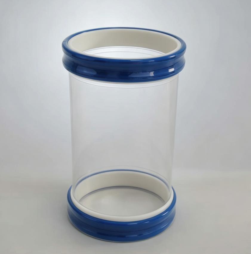
Static Control in Powder Flexible Connectors: A Four-Level Engineering Framework for Combustible Dust Applications
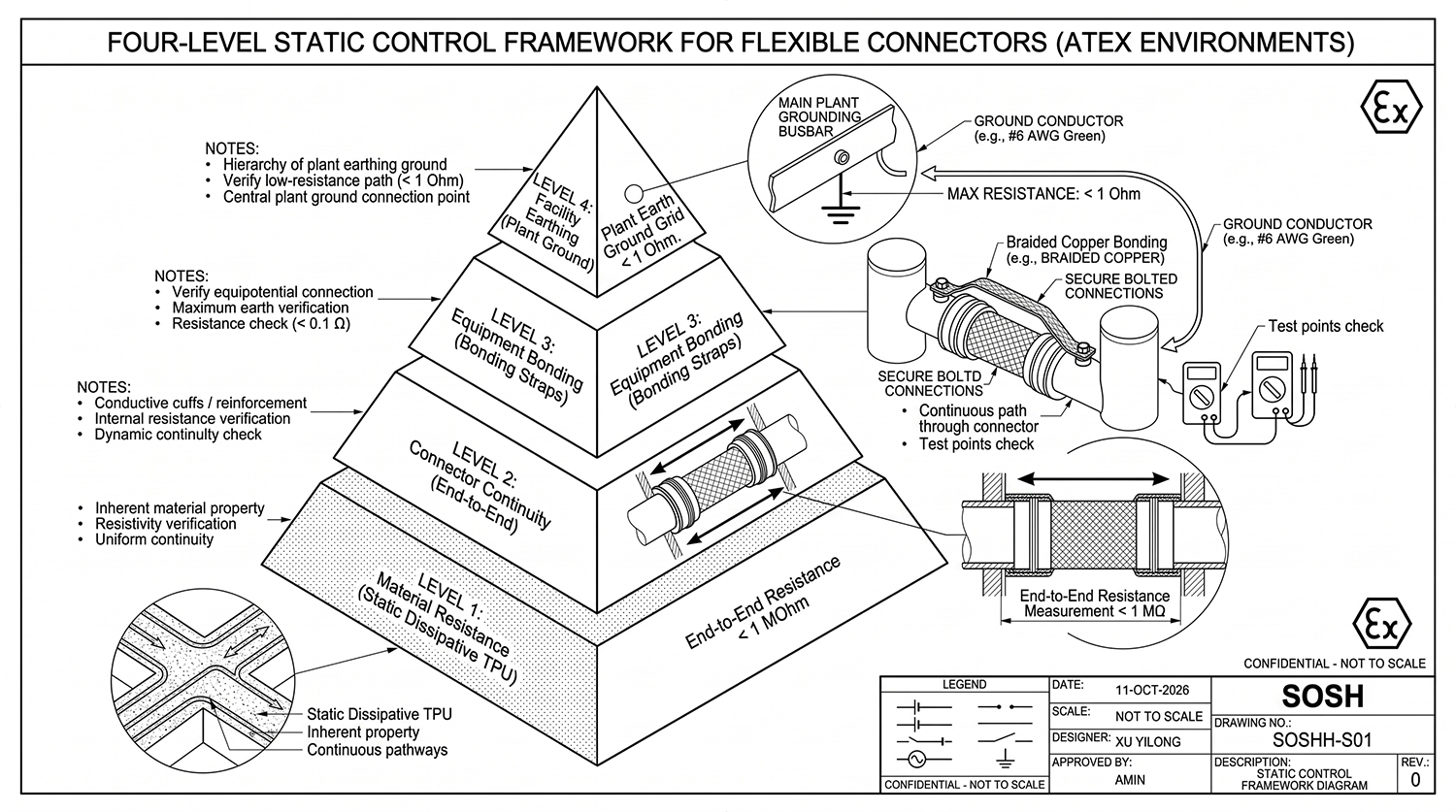
Figure 1: The SOSHH Comprehensive Four-Level Electrostatic Control Framework for powder flexible sleeve installations in ATEX combustible dust environments, ranging from base material resistivity to plant grounding.
Core Engineering Verdict
Static control in combustible powder handling systems is not achieved by selecting a flexible connector with a single “antistatic” specification.
A complete electrostatic safety strategy requires four coordinated control levels:
| Control Level | Engineering Purpose | Verification |
|---|---|---|
| Level 1: Material Performance | Confirm static dissipative TPU properties | Surface resistance testing |
| Level 2: Connector Continuity | Confirm finished sleeve electrical pathway | End-to-end resistance testing |
| Level 3: Equipment Bonding | Prevent isolated metal charge accumulation | Bonding jumper inspection |
| Level 4: Facility Grounding | Provide safe discharge path to earth | Ground resistance measurement |
A static dissipative flexible connector helps control electrostatic charge accumulation, but it does not replace proper equipment bonding or plant grounding.
For food powder, pharmaceutical, chemical, and combustible dust applications, engineers must evaluate the complete electrostatic discharge pathway.
Why Powder Flexible Connectors Require Static Control
During powder conveying, screening, mixing, and discharge processes, particles continuously collide with the internal surface of flexible connectors.
This friction creates electrostatic charge through the triboelectric effect. If the connector material is highly insulating, charge may accumulate and increase the risk of electrostatic discharge.
Typical applications requiring static control include:
| Industry | Application Examples |
|---|---|
| Food Processing | Flour, starch, sugar, dairy powder conveying |
| Pharmaceutical | API powder and ingredient transfer |
| Chemical | Fine powder and additive handling |
| Bulk Material | Hopper, sifter, rotary valve connections |
A common purchasing mistake is assuming that an “antistatic” label alone guarantees safe operation.
Engineers should evaluate four factors together:
- Material electrical properties
- Finished connector continuity
- Equipment bonding
- Facility grounding
Level 1: Static Dissipative TPU Material Selection
The first level evaluates the electrical characteristics of the polymer itself.
Different material resistance ranges provide different electrostatic behaviors:
| Material Type | Typical Resistance | Performance |
|---|---|---|
| Insulating TPU | >10¹² Ω | Charge accumulation risk |
| Static Dissipative TPU | 10⁶–10⁹ Ω/sq | Controlled charge dissipation |
| Conductive TPU | <10⁶ Ω | Faster electrical discharge |
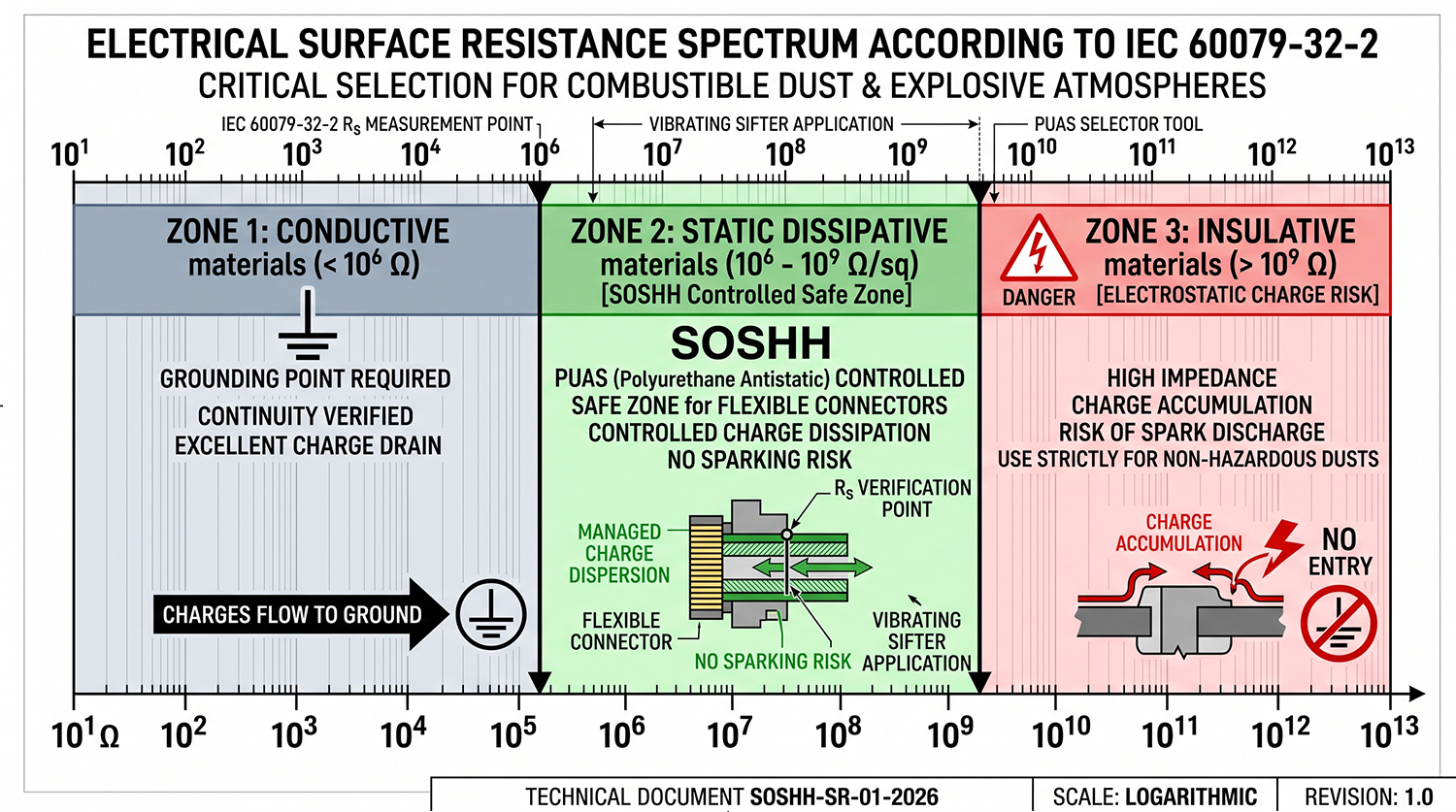
Figure 2: Electrical resistance spectrum per IEC 60079-32-2. Static dissipative TPU (PUAS) maintains controlled surface resistivity between 10⁶ and 10⁹ Ω/sq, preventing both rapid spark discharges and high-impedance static buildup.
For flexible powder connectors, static dissipative TPU is commonly preferred because it provides a balance between:
- Electrostatic control
- Flexibility
- Mechanical durability
- Long service life
SOSHH PUAS static dissipative TPU specifications:
| Parameter | Value |
|---|---|
| Surface Resistance | 10⁶–10⁹ Ω/sq |
| Continuous Temperature | -30 to +110 deg C |
| Peak Temperature | Up to +120 deg C |
| Material Structure | Static dissipative polyether TPU |
A material resistance certificate verifies the polymer performance only. It does not confirm that the finished connector assembly maintains electrical continuity.
Level 2: Finished Connector Electrical Continuity
A flexible connector is a fabricated assembly, not simply a piece of raw TPU material.
Manufacturing processes can influence electrical performance:
| Component | Potential Impact |
|---|---|
| Heat-welded seams | May interrupt resistance pathway |
| Reinforcement layers | May affect electrical continuity |
| Cuffs and clamps | May influence connection reliability |
| Internal structures | May create isolated sections |
Finished connector verification should include:
| Test | Purpose |
|---|---|
| Cuff-to-cuff resistance measurement | Confirm continuous dissipation path |
| Weld seam inspection | Verify fabrication quality |
| Assembly testing | Confirm installed performance |
The correct engineering question is not:
“Is the TPU material antistatic?”
The correct question is:
“Does the complete installed connector provide reliable static dissipation?”
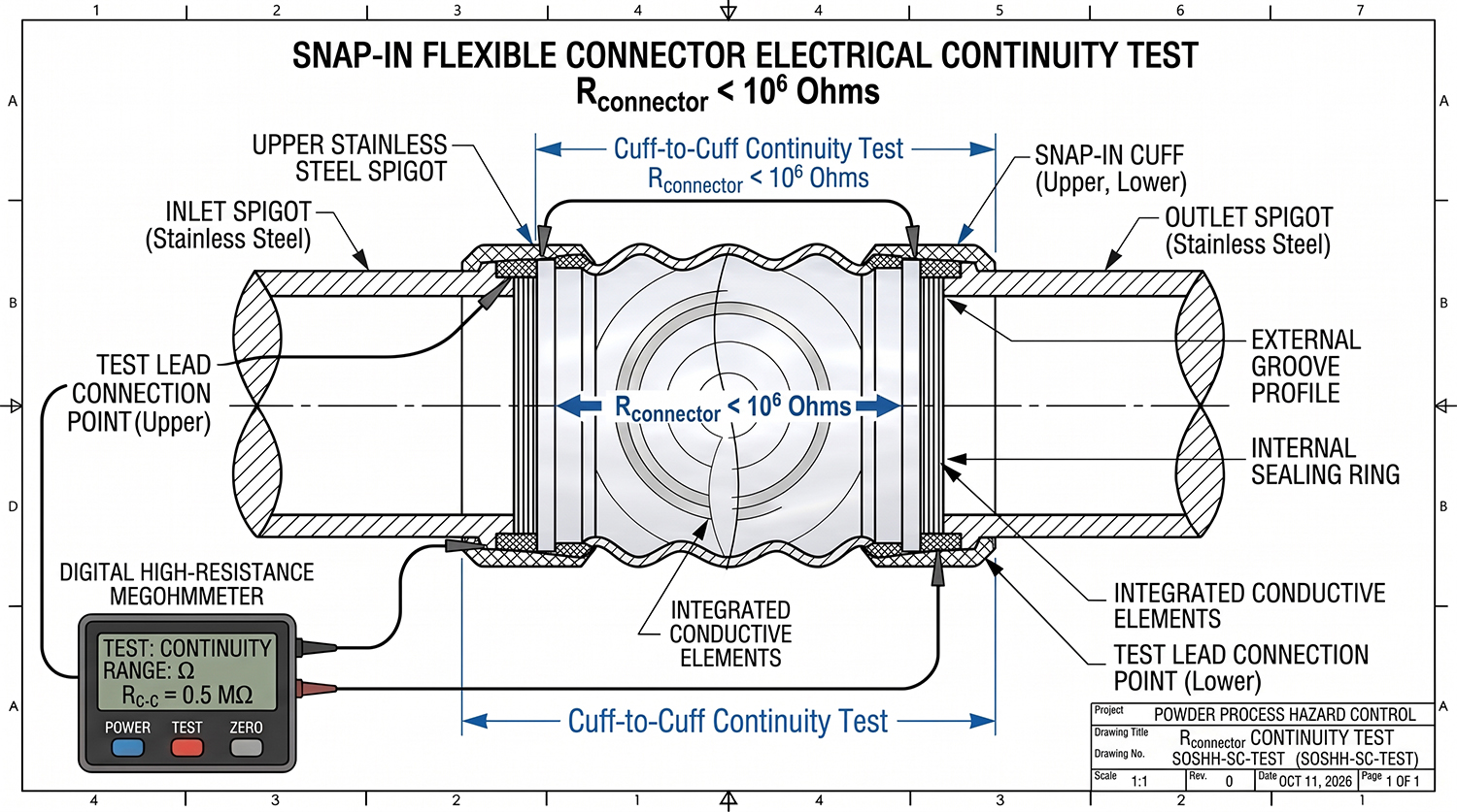
Figure 3: Cuff-to-cuff electrical continuity verification (R_connector < 10⁶ Ω) on a finished SOSHH snap-in connector. Checking the full fabrication ensures seams, cuffs, and rings do not break the discharge path.
Level 3 & Level 4: Equipment Bonding and Facility Grounding
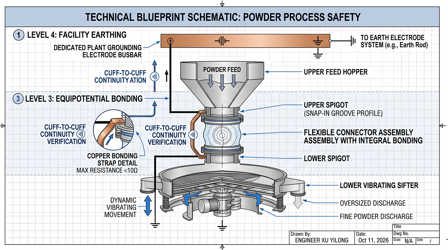
Figure 4: Complete electrical discharge path. Equipotential copper bonding jumpers (Level 3) bridge across the flexible connector to eliminate potential differences, routing safe dissipation (Level 4) to the plant ground electrode (R_earth < 1 Ω).
Static control cannot rely only on the flexible connector material.
Flexible connectors commonly connect:
- Stainless steel hoppers
- Vibrating sifters
- Rotary valves
- Dust collectors
- Powder processing equipment
The complete grounding path should be:
| Electrostatic Path | Function |
|---|---|
| Powder movement | Generates charge |
| Static dissipative connector | Controls charge accumulation |
| Metal equipment bonding | Maintains electrical continuity |
| Plant grounding system | Safely removes charge |
Equipment bonding should include:
- Grounding straps
- Bonding jumpers
- Verified metal-to-metal continuity
The flexible connector should never be considered the only electrical connection between process equipment.
How to Select the Correct Static Dissipative Flexible Connector
Before purchasing a connector for powder handling applications, engineers should provide:
| Selection Factor | Required Information |
|---|---|
| Powder Characteristics | Material type, moisture, dust properties |
| Mechanical Conditions | Diameter, vibration, pressure, vacuum |
| Temperature | Operating and cleaning temperature |
| Cleaning Method | Dry cleaning, CIP, chemicals |
| Safety Requirements | ATEX zone, MIE, grounding requirements |
A correct specification considers both electrostatic safety and mechanical service life.
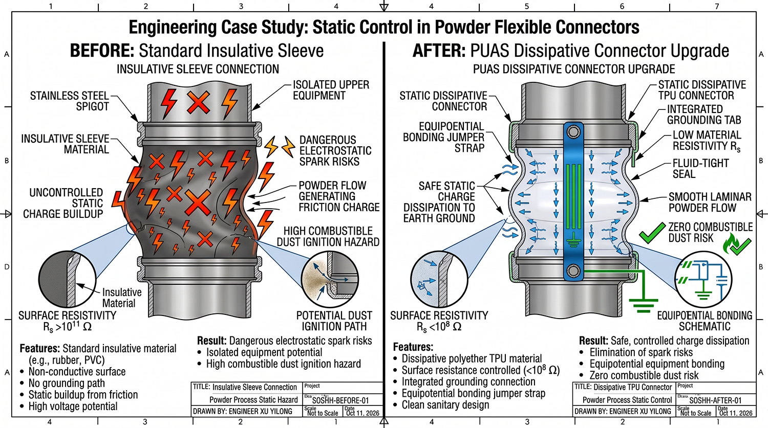
Figure 5: On-site case study on a powder sifter connection. Replacing a hazardous, ungrounded insulative sleeve (susceptible to friction charge and sparking) with a certified SOSHH PUAS dissipative snap-in connector integrated with equipotential bonding.
Engineering Case Study: Static Control Upgrade for Powder Sifter Connection
A food powder manufacturer required a flexible connector solution for a vibrating sifter application.
The existing connector had no documented static performance and the electrical discharge pathway was unclear.
SOSHH supplied:
| Item | Solution |
|---|---|
| Material | Static dissipative polyether TPU |
| Electrical Performance | Controlled 10⁶–10⁹ Ω/sq resistance |
| Verification | Finished connector continuity testing |
| Support | Installation and grounding recommendations |
The upgraded solution improved static control reliability, maintenance inspection confidence, and application documentation.
Frequently Asked Questions
| Question | Answer |
|---|---|
| Does an antistatic flexible connector replace grounding? | No. Equipment bonding and plant grounding are still required. |
| What resistance range is suitable for static dissipative TPU? | Typically 10⁶–10⁹ Ω/sq for controlled charge dissipation. |
| Is conductive TPU always better than static dissipative TPU? | No. Static dissipative TPU often provides a better balance of flexibility and safety. |
| Can static dissipative connectors be used in ATEX applications? | Yes, when integrated into a complete electrostatic risk-control system. |
| How can SOSHH help with connector selection? | Send photos, dimensions, and operating conditions for engineering review. |
Engineering Support from SOSHH
Selecting the correct powder flexible connector requires more than choosing a diameter or material name.
Send SOSHH:
- Equipment photos
- Existing connector photos
- Installation dimensions
- Powder type
- Operating temperature
- Cleaning requirements
- Static control requirements
Our engineering team can provide:
✓ Material selection
✓ Connector structure recommendations
✓ Technical drawing support
✓ Prototype development
Application photos + operating conditions → Engineering recommendation → Drawing → Sample arrangement
Contact SOSHH for technical support on powder handling flexible connector applications.