





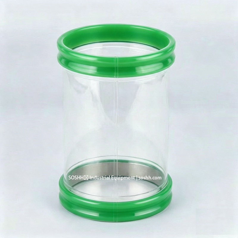
Why Vibrating Sifter Flexible Sleeves Tear at the Clamp Edge
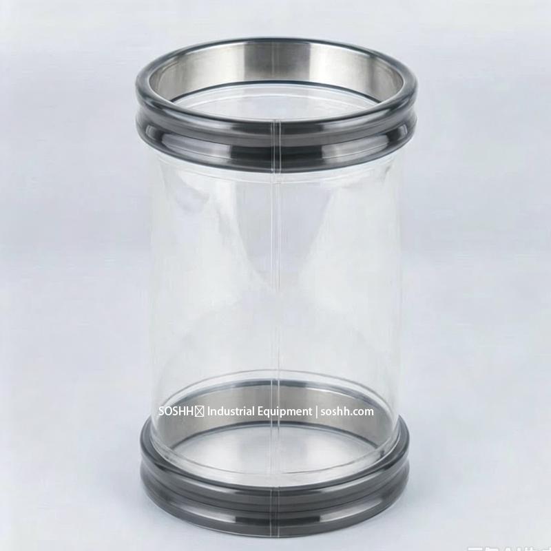
The tear is rarely a raw material defect — it is a mechanical load-path design error. A flexible sleeve on a vibratory screener flexes continuously while being gripped by a rigid band at the precise point of maximum bending moment. The clamp edge converts a distributed flex radius into a localized hinge line, concentrating cyclic shear stress into a narrow 2–4 mm boundary. Under typical production cycles, mechanical failure is inevitable if the load is not redirected.
Vibrating sifter flexible sleeve tearing at the clamp edge is driven by mechanical stress concentration at the rigid clamp pinch point under high-frequency dynamic shear (20–30 Hz), compounded by CIP chemical embrittlement and over-tightening. The engineering fix is a virgin polyether TPU sleeve (Shore A 85, 110 kN/m tear, >1,000,000 cycles) with HF-welded exterior pockets that relocate clamp load off the flexing crease.
1. Failure Mechanics: Four Dynamic Loads Acting Concurrently
- Pinch-Point Stress Concentration: A rigid worm-drive clamp or band applies 40–60 N·m of radial hoop force. Under 20–30 Hz screening motion, this rigid-to-flexible junction acts as a severe stress raiser, amplifying nominal flexural fatigue by 3× to 5× and causing micro-fissures within 300–500 operating hours.
- High-Frequency Dynamic Shear Fatigue: The sleeve wall is subjected to continuous multi-axis shear between the stationary spigot and the oscillating deck. Thin-wall films (<0.8 mm) lacking tear-energy headroom below 80 kN/m quickly propagate fatigue cracks along the shear path.
- Hydrolytic & Chemical Attack from CIP: Polyester-based polyurethanes exposed to warm water or caustic washdowns (2–5% concentration at 60–80 °C) suffer rapid ester-chain cleavage. Hydrolysis cuts tear strength by 40–60% over 10–14 weeks, causing the sleeve to fail prematurely along the stressed clamp line.
- Triboelectric Charge Accumulation: Fast-moving dry particles across insulating sifter walls generate massive triboelectric surface charges. Without certified static dissipation, localized dielectric breakdown and electrical pitting further weaken polymer chains in combustible dust zones.
2. Engineering Solutions: Isolating Hoop Load from the Flex Zone
| Failure Input | Conventional Ineffective Fix | SOSHH Engineered Solution |
| Rigid clamp crushes flexing crease | Torquing the clamp tighter | HF-welded exterior cuff pockets: Moves the clamp into an isolated channel outside the flex path; bending zone remains compliant. |
| Dynamic flex fatigue (>1,000,000 cycles) | Increasing wall thickness (adds stiffness and heat build-up) | Virgin polyether TPU (Shore A 85, 110 kN/m tear): Retains high elastomeric recovery and flex-fatigue life from -20 °C to +110 °C. |
| CIP caustic hydrolysis | Switching to silicone (poor tear and dynamic abrasion life) | Pure polyether backbone: Hydrolytically stable ether linkages completely resist microbial attack and wet washdowns. |
| Operator over-tightening cuts | Adding rubber/metal shims under the band | Tool-free polymer snap-band system: Internal spring-tension band locks into rolled spigot grooves with calibrated, zero-tooling preload. |
| Static spark / Dust explosion risk | External bare copper grounding wires | PUAS anti-static TPU: Tested to IEC 60079-32-2, delivering permanent 10⁶ to 10⁹ Ω surface resistivity across the entire sleeve body. |
3. Selection Matrix: Matching Sleeve Design to Sifter Duty
| Sifter Operating Duty (Hz / Stroke) | Spigot Diameter (mm) | Installation Gap (IG) | Recommended Material Grade | Cuff & Reinforcement Structure |
| Light Sifting (15–20 Hz / ±3 mm) | 150 – 300 mm | 15 – 25 mm | 80 Shore A Polyether TPU | Single snap-band, HF welded cuffs |
| Standard Screener (20–25 Hz / ±5 mm) | 300 – 600 mm | 20 – 35 mm | 85 Shore A Polyether TPU (110 kN/m) | Dual snap-band, isolated cuff pockets |
| Heavy-Duty / Ultrasonic (25–30 Hz / ±7 mm) | 600 – 900 mm | 30 – 50 mm | 90 Shore A Reinforced Polyether | Isolated cuff pockets + internal 316L support rings |
| Sanitary Food / Dairy CIP (>20 Hz / daily wash) | 200 – 800 mm | 25 – 40 mm | FDA Polyether (CFR 177.2600 / TQT4821B36E) | Mirror-smooth inner bore, zero-crevice tool-free cuffs |
Critical Sizing Parameter — Installation Gap (IG): The IG is the vertical distance between the two rigid spigot lips under static load. If IG is too large, the sleeve wall buckles into a double-radius "S-curve" that doubles internal bending stress. If IG is too tight, the sleeve remains under constant tensile tension, accelerating fatigue.
4. Three Common Field Installation Traps
- The "Extra Length is Safer" Fallacy: Specifying an extra 50 mm of sleeve length to "give it room" creates excessive wall slack. Under vibratory stroke, this excess slack folds against itself, forming secondary abrasive wear creases that slice open in days.
- Reusing Old Clamps with Gouged Edges: Stamped worm-drive hose clamps develop razor-sharp inner burrs over time. Clamping these onto a new polyurethane sleeve creates a physical notch that initiates dynamic crack propagation.
- Ignoring Spigot Groove Depth: Ordering by spigot outer diameter (OD) alone without accounting for roll-formed groove depth causes incorrect band seating, leading to snap-band dislocation or localized rim pinching.
Technical Specification & Sizing Checklist
Before ordering replacement sleeves for vibratory sifters or screeners, confirm the following six parameters:
- [ ] Sifter Kinematics: Document running frequency (Hz) and 3D stroke amplitude (mm).
- [ ] Exact Dimensions: Measure spigot OD, roll groove depth, and static installation gap (IG).
- [ ] Polymer Specification: Verify virgin polyether TPU (Shore A 85, >100 kN/m tear strength; avoid recycled resin or polyester TPU).
- [ ] Food Compliance: Confirm FDA 21 CFR 177.2600 (Test Ref: TQT4821B36E) and plasticizer-free formulation for sanitary milk/sugar powders.
- [ ] Static Control: Specify 10⁶ to 10⁹ Ω resistivity tested to IEC 60079-32-2 if handling combustible dusts.
- [ ] Connection Style: Replace sharp worm-drive clamps with tool-free internal snap-bands or isolated external pocket sleeves.
Frequently Asked Questions (FAQ) — Sifter Sleeve Failure Analysis
Q1: Why does a sifter flexible sleeve tear along the clamp edge rather than the body center?
A: The clamp edge creates a rigid-to-flexible mechanical boundary. Under 20–30 Hz continuous vibration, this boundary acts as a stress raiser of 3× to 5× nominal flexural load. All bending moments are concentrated onto a 2–4 mm pinch line, causing dynamic flex-fatigue tearing at the crease while the center sleeve remains intact.
Q2: Can I prevent tearing by simply specifying a thicker sleeve wall?
A: No. Increasing wall thickness increases mechanical stiffness and bending resistance, which actually accelerates internal heat build-up and flex fatigue under high-frequency stroke. The correct solution is an elastomeric material with superior tear energy (virgin polyether TPU, Shore A 85, 110 kN/m) and an isolated cuff geometry.
Q3: Why does CIP washdown cause premature failure at the clamp line?
A: Conventional polyester-based polyurethanes undergo ester-chain hydrolysis when exposed to caustic CIP washdowns (2–5% at 60–80 °C). This drops tear strength by 40–60%. Because the clamp line is already under hoop stress, hydrolytic embrittlement causes it to slice open rapidly. Virgin polyether TPU is hydrolytically stable and prevents this degradation.
Q4: How do HF-welded cuff pockets prevent clamp-edge pinching?
A: High-frequency welded exterior pockets physically isolate the clamping band into a dedicated outer channel. The rigid clamp hoop tension is absorbed entirely by the reinforced pocket, leaving the internal flexing wall uncompressed and free to absorb multi-axis vibratory strokes.
Q5: What is the most critical dimension to avoid sifter sleeve creasing?
A: The static Installation Gap (IG). If the gap between the upper and lower spigot is too large, the sleeve collapses into a double-curve "S-bend" that creates secondary friction wear points. If the IG is too small, the sleeve operates under constant tensile stretch. Always size the sleeve to the exact measured IG.
Browse all vibration, tearing and material questions in the Sifter Sleeve FAQ Hub..
For custom dimensional review, CAD drawings, or static dissipation calculations, contact the SOSHH engineering team at amin@soshh.com with your operating frequency and spigot dimensions.