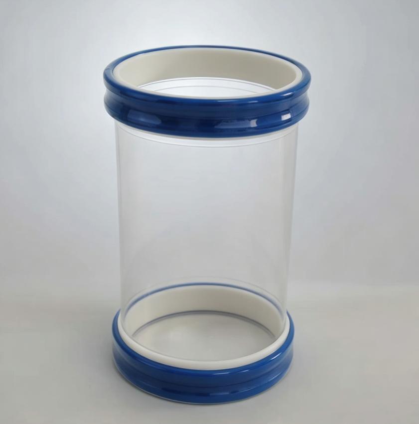
![SOSHH Inflatable Snap-In Flexible Connector in Deflated State for FIBC Neck Insertion]()
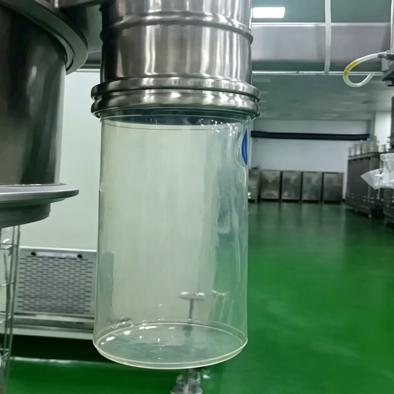
![SOSHH Pneumatic FIBC Loading Seal Inflated at 1.5 Bar for Dust-Free Big Bag Filling]()
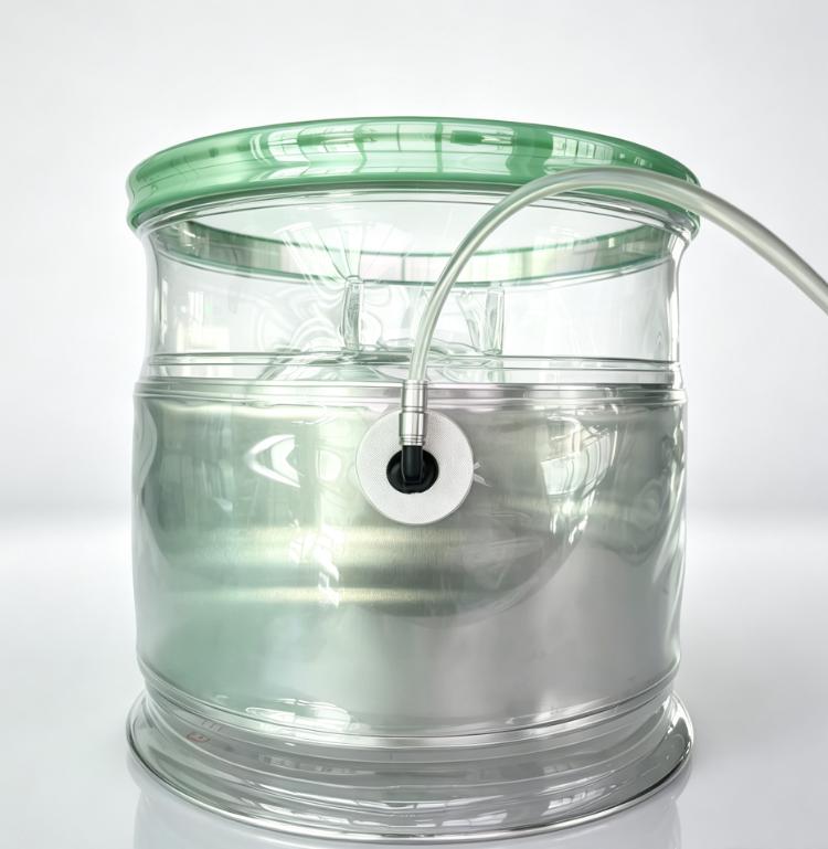
![SOSHH inflatable snap-in flexible connector with grey snap cuffs and pneumatic expansion bladder for dust-tight FIBC bulk bag loading]()
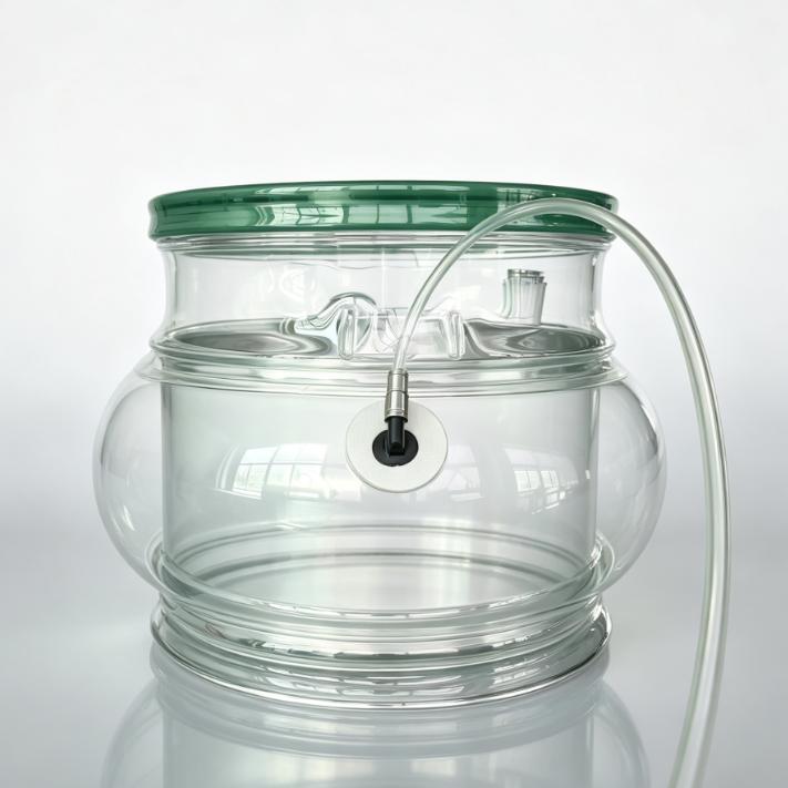
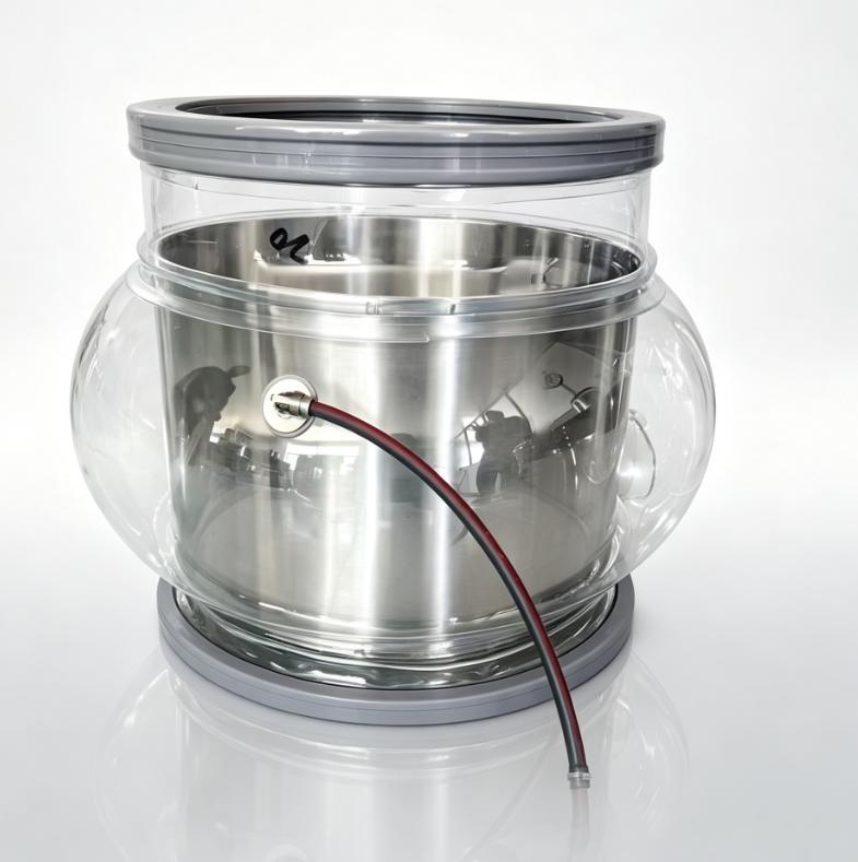
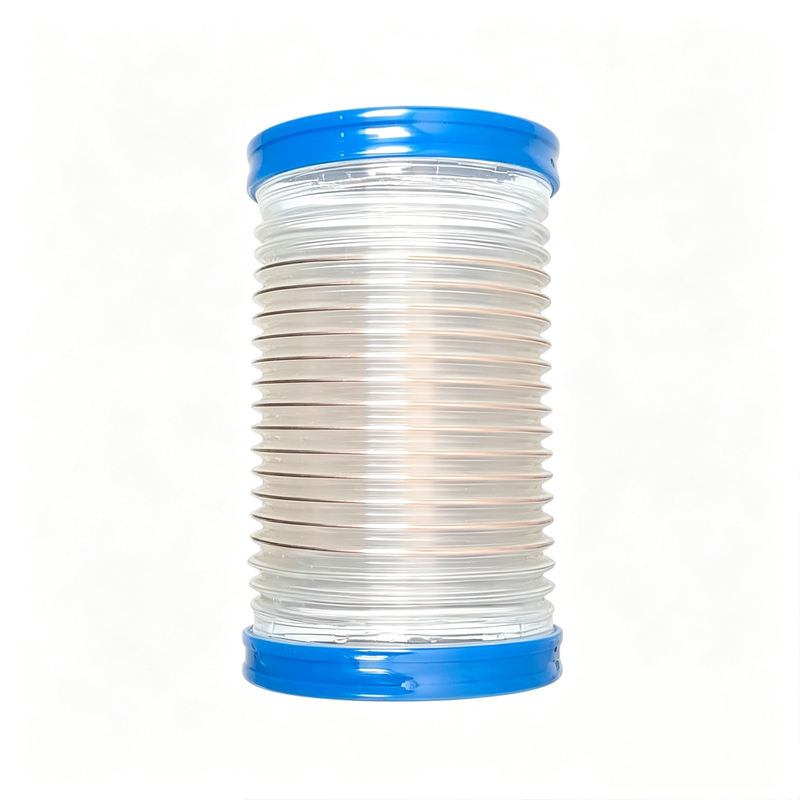
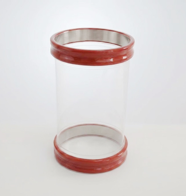
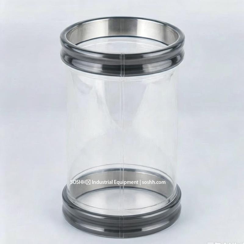
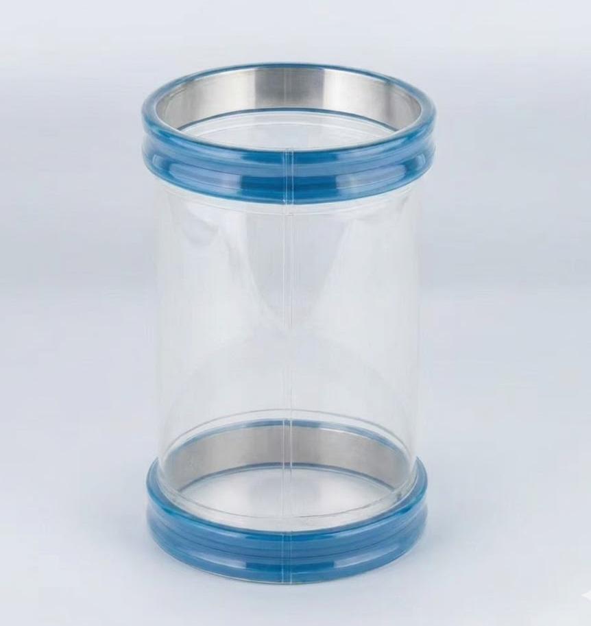
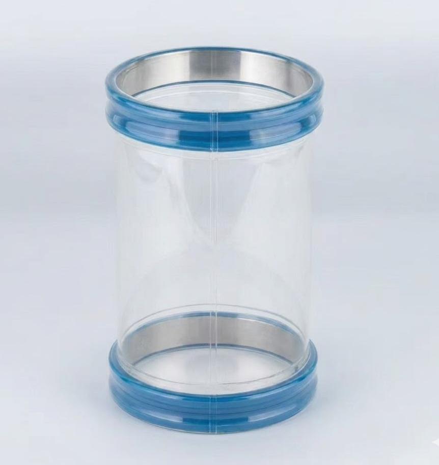
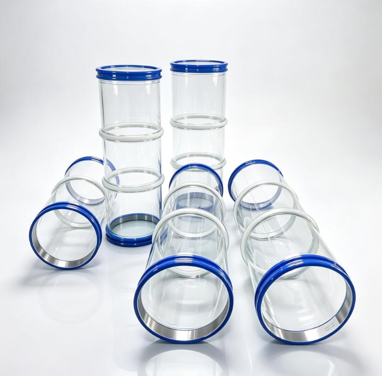
The SOSHH inflatable FIBC connector uses a pneumatic bladder to apply radial sealing force around a bulk-bag neck during filling or discharge. The current configuration operates at 1.0–2.0 bar and is available in standard diameters from DN150 to DN600. Final pressure, sealing geometry and usable expansion range depend on the FIBC neck, liner construction, engagement length and process conditions. Specify the complete interface rather than nominal bag capacity alone.
1. How the Inflatable FIBC Seal Works
The sealing system has four functional zones:
Rigid Process Spout → Inflatable Bladder → FIBC Neck / Liner → External Mechanical Support
Step 1 — Install the connector. The connector is installed onto the compatible rigid spigot using the snap-in connection geometry. Connection dimensions should be checked before the FIBC is attached.
Step 2 — Position the FIBC neck. The FIBC inlet neck and liner are positioned over the deflated sealing section and fully seated within the specified engagement area. Confirm the actual neck geometry supplied by the FIBC manufacturer rather than relying on nominal bag dimensions.
Step 3 — Inflate the bladder. Compressed air is supplied through the push-in fitting. The bladder expands radially and applies normal force around the FIBC neck. Required pressure is configuration-specific — 1.0–2.0 bar is the published range for the current configuration, not a universal standard.
Step 4 — Fill or discharge. The process operates while the bladder maintains the specified sealing condition.
Step 5 — Deflate for release. The pneumatic circuit is vented through the controlled exhaust path; the bladder retracts and the FIBC neck is removed.
2. Engineering Specifications
| PARAMETER | CURRENT CONFIGURATION | ENGINEERING NOTE |
|---|
| Connector type | Inflatable flexible FIBC seal | Pneumatic radial sealing |
| Flexible material | Ether-based TPU, transparent | Confirm exact grade during RFQ |
| Operating air pressure | 1.0–2.0 bar (14.5–29.0 psi) | Product-specific range |
| Pneumatic connection | 6 mm / 8 mm push-in fitting | Final fitting standard to be confirmed |
| Standard diameter range | DN150–DN600 | Custom dimensions available |
| Installed length | 150–800 mm | Final length per equipment geometry |
| Inflation expansion | 20–50 mm radial movement per side | Configuration-dependent |
| Spigot material | AISI 304 or AISI 316L stainless steel | Confirm material and finish |
| Product-contact geometry | Smooth internal flow path | Verify final assembly |
| Temperature | −30 to +85 °C continuous (peak +110 °C; 85 °C CIP) | Ether-based TPU substrate |
| Cycle qualification | Available by configured assembly | Test pressure, temperature, cycle criteria must be specified |
| Food-contact documentation | Available for specified grades/configurations | Verify exact material and intended use |
| Custom geometry | Available | Diameter, length, air-port orientation, sealing geometry |
| Drawing support | 2D / 3D CAD available | Final dimensions confirmed from RFQ |
Troubleshooting Matrix
| Symptom | Direct Mechanism | Diagnostic Check | Corrective Action |
|---|
| Dust escapes around the bag neck | Incomplete circumferential contact | Inspect neck OD, liner folds and bladder expansion around the full circumference | Confirm actual neck dimensions and adjust sealing configuration |
| Bag neck slips during filling | Insufficient retention force or dynamic movement | Check inflation pressure and axial movement while filling | Review bladder pressure range, engagement length and bag support |
| Liner wrinkles inside the sealing zone | Non-uniform compression | Inspect liner position before and after inflation | Improve liner positioning and sealing geometry |
| Bladder deflates slowly | Restricted pneumatic exhaust path | Measure deflation time with and without the FIBC installed | Check valve, tubing, fitting and exhaust flow |
| Powder accumulates above the sealing area | Local geometry creates a retention zone | Inspect after a representative filling cycle | Review insertion depth, seal geometry and cleaning access |
| Seal works empty but leaks during filling | Dynamic pressure or movement changes the interface | Test at actual filling rate and dust-extraction condition | Perform dynamic qualification under production conditions |
| Bladder shows premature wear | Excessive pressure, local abrasion or repeated flexing | Inspect wear location and expansion path | Review pressure limit, clearance, material and cycle conditions |
3. FIBC Neck Compatibility Is the First RFQ Variable
An inflatable seal should not be selected from FIBC capacity alone. Specify the actual neck inside diameter, neck outside diameter, neck length, liner material, liner thickness, liner construction, fabric construction, allowable neck variation, insertion depth and sealing engagement.
ISO 21898:2024 specifies materials, construction, design, type testing and marking requirements for FIBCs intended for non-dangerous solid materials; it does not establish one universal filling-neck diameter for every commercial FIBC.
FIBC Neck RFQ Matrix
| PARAMETER | REQUIRED INPUT |
|---|
| Nominal neck ID | ____ mm |
| Nominal neck OD | ____ mm |
| Actual measured neck OD | ____ mm |
| Neck length | ____ mm |
| Flat width, if supplied | ____ mm |
| Liner material | LDPE / PE / multilayer / other |
| Liner thickness | ____ μm |
| Liner construction | Form-fit / tubular / gusseted / other |
| FIBC type | A / B / C / D / other |
| Fabric | PP / coated PP / other |
| Required sealing length | ____ mm |
| Insertion depth | ____ mm |
| Allowable dimensional variation | ____ mm |
4. Liner Compatibility
The liner is part of the sealing interface. Two bags with the same nominal neck diameter can behave differently if their liners have different thickness, stiffness, surface friction, fold memory, multilayer construction or surface treatment.
Common liner categories:
- PE-based liners — used widely for powder containment.
- Form-fit liners — designed to follow the bag geometry closely.
- Tubular or gusseted liners — can introduce folds and local thickness variation around the neck.
- Barrier liners — multilayer structures can have different compression and friction characteristics from single-layer PE film.
- Electrostatic-control liners — where combustible dust is involved, the FIBC and liner classification must be specified separately from the connector. IEC 61340-4-4 addresses electrostatic classification and testing of FIBCs and their inner liners, including Type A, B, C and D constructions.
5. Inflation Pressure: Do Not Use a Universal Setpoint
The current configuration is published at 1.0–2.0 bar operating air pressure. This is the operating envelope of the selected seal, not a universal standard for all inflatable FIBC systems.
Required pressure depends on bladder geometry, neck diameter, liner thickness, sealing engagement, liner friction, allowable neck compression, dynamic load and retention requirement.
Pressure-Control Hardware
A typical pneumatic circuit may include:
Compressed Air → Regulator → Gauge → Isolation / Control Valve → Inflatable Bladder
Where required, add pressure relief, controlled exhaust, pressure switch, pressure monitoring and a cycle counter. The selected pressure limit should be below the verified pressure capability of the bladder assembly and pneumatic components.
Sealing Force and Bag-Neck Protection
Increasing inflation pressure does not automatically produce a better seal. A useful first-order relation is:
F_N ≈ ΔP × A_eff
Where F_N is the effective normal sealing force, ΔP is the bladder pressure differential, and A_eff is the effective pressure area.
- Too little normal force: powder leakage, neck slip, leakage through liner folds, sensitivity to bag variation.
- Too much local compression: liner deformation, folds, abrasion, tearing, difficult release.
The acceptance criterion should be based on the actual FIBC material rather than a universal pressure number.
6. Filling and Discharge Are Different Operating Conditions
FIBC filling: powder inflow + displaced air + entrained air + bag expansion + head movement. The filling head must accommodate displaced air while maintaining containment. Industrial bulk-bag filling systems commonly use double-casing or double-jacket filling heads to balance material and air volume and route displaced air and fines into a dust-collection system.
FIBC discharge: material leaves the bag, the bag neck can move as the bag collapses, local deformation can increase, and air balance depends on the downstream process.
The inflatable seal should be qualified for the actual intended mode: Filling / Discharge / Both.
7. Dust Extraction Is a System-Level Requirement
An inflatable seal contains the powder/air interface; it does not determine the required dust-collector airflow by itself.
A first-order estimate of displaced gas volume is:
Q(displaced) = (ṁ powder ÷ ρ bulk) + Q(entrained air)
Where Q(displaced) is the gas volume that must leave or be accommodated, ṁ powder is the powder mass flow, ρ bulk is the bulk density, and Q(entrained air) is the additional process air.
The actual dust-extraction requirement also depends on filling-head geometry, pre-inflation air, conveying air, vent-path resistance, dust-collector capacity, bag size and filling rate. Specify extraction airflow, extraction pressure, duct diameter, pressure at the filling head and filling rate. Do not specify a universal negative-pressure setpoint without system testing.
8. Electrostatic and Hazardous-Area Requirements
For combustible powders, the flexible connector is only one part of the electrostatic-control system.
The RFQ should identify:
- Powder classification
- Hazardous-area classification
- FIBC Type
- Liner type
- Grounding requirements
- Conductive components
- Static-dissipative material requirements
IEC 61340-4-4 provides requirements and test methods for electrostatic classification of FIBCs and liners. Do not treat a connector’s electrical resistance result as a substitute for the complete hazardous-area assessment.
9. Food and Pharmaceutical Applications
For food, nutraceutical and pharmaceutical applications, document the exact material and intended-use conditions. Confirm polymer grade, additives, liner material, sealing components, temperature, contact duration, cleaning process and regulatory basis.
Avoid generic statements such as “FDA certified” unless the exact finished configuration and intended use are covered by the referenced documentation. For FIBCs, ISO 21898:2024 covers construction, design, testing and marking for containers intended for non-dangerous goods.
10. Qualification and FAT/SAT
The inflatable connector should be qualified with the actual or representative FIBC neck.
- Dimensional Fit — verify spout diameter, neck diameter, neck length, engagement and insertion depth.
- Static Seal Test — inflate under the specified operating condition and inspect the full circumference.
- Neck Retention Test — apply the expected axial force and monitor movement.
- Dynamic Filling Test — run the actual process or an approved process simulant.
- Liner Compatibility Test — repeat with the actual liner.
- Inflation / Deflation Cycle Test — use the customer-defined lifecycle target.
- Pressure-Control Test — verify regulation, pressure stability, relief and controlled exhaust.
- Temperature Test — test at relevant operating and cleaning temperatures.
- Dust-Extraction Test — run under the actual filling-head ventilation condition.
- Post-Test Inspection — inspect bladder, neck contact area, sealing surface, air fitting, snap-in connection, welds and liner condition.
Acceptance criteria should be written into the project specification before FAT.
11. Troubleshooting
| SYMPTOM | LIKELY CAUSE | ENGINEERING CHECK | CORRECTIVE ACTION |
|---|
| Powder escapes around neck | Uneven sealing | Neck OD + liner folds + inflation pressure | Recheck geometry and seating |
| Neck slips during filling | Insufficient retention | Dynamic axial load | Review pressure and engagement |
| Liner wrinkles | Excessive local compression | Liner thickness and insertion depth | Adjust geometry / insertion method |
| Slow release | Restricted pneumatic exhaust | Valve + tubing + fitting | Improve exhaust path |
| Powder accumulates near seal | Local ledge or fold | Visual inspection after filling | Revise insertion and sealing geometry |
| Works empty but leaks during filling | Dynamic process load | Test at production filling rate | Perform dynamic qualification |
| Bladder wears early | Excessive strain or interference | Inspect expansion path | Review pressure, clearance and cycling |
12. Custom Engineering
Every FIBC filling station has a finite interface envelope. The connector can be configured around non-standard diameters, installed lengths, sealing-zone geometry, pneumatic-port orientation, spigot configuration, FIBC neck dimensions, liner construction and filling-head movement.
Standard diameters cover DN150 to DN600 and installed lengths from 150 to 800 mm, with custom dimensions available.
Custom RFQ Inputs
Provide: Spout OD + Neck OD + Neck Length + Liner Thickness + Available Air Pressure + Filling Rate + Dust Extraction Condition
Then add: Temperature + Cleaning + FIBC Type + Powder + Required Cycle Life
RFQ Specification Checklist
FIBC
- FIBC neck OD: ____ mm
- FIBC neck ID: ____ mm
- Neck length: ____ mm
- Bag-neck flat width, if available: ____ mm
- FIBC Type: A / B / C / D
- Liner material: __________
- Liner thickness: ____ μm
- Liner construction: Form-fit / Tubular / Gusseted / Multilayer / Other
Process
- Powder: __________
- Bulk density: ____ kg/m³
- Particle size: __________
- Filling rate: ____ kg/h
- Target bags/hour: ____
- Filling / discharge / both: __________
- Operating temperature: ____ °C
- Cleaning temperature: ____ °C
- Cleaning method: __________
Pneumatic System
- Available air pressure: ____ bar
- Required operating pressure: ____ bar
- Air tubing OD: ____ mm
- Fitting standard: Push-in / BSP / NPT / Other
- Pressure monitoring required: Yes / No
- Relief valve required: Yes / No
- Automatic deflation: Yes / No
Filling-Head / Dust Extraction
- Dust-extraction airflow: ____ m³/h
- Pressure at filling head: ____ Pa
- Vent connection diameter: ____ mm
- Fill-head movement: ____ mm
- Dynamic stroke: ____ mm
Compliance
- Food contact: Yes / No
- FDA documentation required: Yes / No
- EU food-contact documentation required: Yes / No
- Hazardous-area requirement: Yes / No
- Zone: 20 / 21 / 22 / Other
- FIBC electrostatic type: C / D / Other
- Metal detector downstream: Yes / No
Drawings
- Spout drawing attached: Yes / No
- FIBC drawing attached: Yes / No
- Existing connector photo attached: Yes / No
- Machine 2D/3D drawing attached: Yes / No
Commercial
- Prototype quantity: ____
- Annual quantity: ____
- Required delivery date: ____
- Replacement / OEM project: __________
13. Primary Industrial Applications
- FIBC bulk-bag filling and discharge stations
- IBC tote charging and reactor drop chutes
- Powder charging and transfer
- Pharmaceutical powders
- Food and ingredient powders
- Battery materials and fine-powder handling
- OEM bulk-bag filling heads
- Enclosed filling stations with dust extraction
14. Request an Inflatable FIBC Seal Review
FIBC
- Neck OD / ID
- Neck length
- Liner material
- Liner thickness
- FIBC type
Process
- Powder
- Bulk density
- Filling rate
- Filling temperature
- Cleaning method
- Filling / discharge mode
Equipment
- Spout OD
- Installed length
- Available air pressure
- Pneumatic fitting
- Dust extraction airflow and pressure
- Machine movement
Compliance
- Food contact
- Pharmaceutical use
- Hazardous-area requirement
- FIBC electrostatic type
- Static-control requirement
Qualification
- Required cycle count
- Retention criteria
- Leakage criteria
- Temperature test
- Cleaning test
Frequently Asked Questions
What air pressure does the inflatable FIBC seal require? The current configuration is published at 1.0–2.0 bar. Final setting depends on bladder configuration, bag-neck geometry and liner condition.
What FIBC neck sizes are supported? Current standard configurations cover DN150–DN600, with custom dimensions available. Actual FIBC neck OD, ID and length should be confirmed during RFQ.
Can it be used for both FIBC filling and discharge? Yes, but the sealing and movement conditions should be qualified for the actual operating mode.
Can it work with PE liners? Yes, subject to actual liner geometry, thickness, friction and sealing engagement.
Is the seal suitable for combustible powders? The connector should be specified as part of the plant’s electrostatic and hazardous-area control system. FIBC type, liner type, grounding and applicable hazardous-area requirements must be identified.
Can you make a custom FIBC seal? Yes. Custom diameter, length, pneumatic-port orientation and sealing geometry can be reviewed from the machine drawing and actual FIBC neck dimensions.