





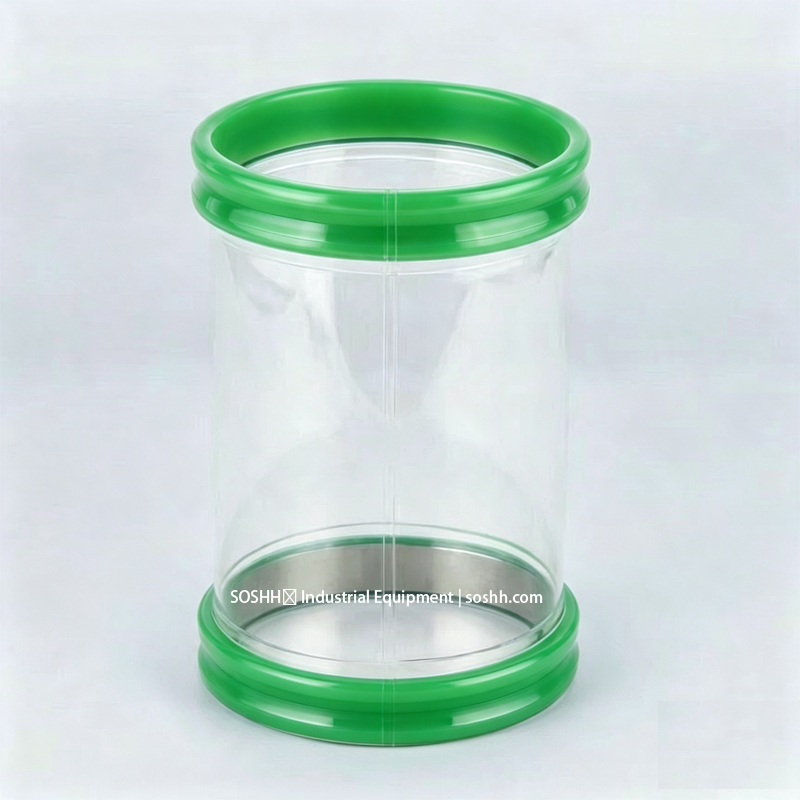
Your Flexible Connector Is the Hidden Source of Unplanned Downtime
When a vibrating screen, feeder or filter “stops for no reason,” the motor, bearing and controller are usually fine. The failure is often the flexible connector — and it fails in ways that masquerade as equipment problems:
- Powder leaking at the joint is read as a worn gasket or a bad clamp.
- A drifting weight signal is read as a load-cell fault.
- A choked bore is read as bridging or rat-holing.
- A sleeve that tears every few weeks is read as “cheap material.”
The sleeve is the cheapest part in the failure chain — yet a cracked cuff, a collapsed wall or a loosened clamp can idle an entire line, trigger a quality hold and force a full teardown. The buyers we hear from say the same thing: the equipment vibrates and the rigid metal chute offers no damping; the fabric sleeve wears out and gets replaced constantly. Both end in the same place — unplanned downtime blamed on the wrong component.
Replacing a sleeve on a schedule costs a fraction of one emergency stop. Diagnosing it correctly costs even less. This guide explains the four hidden failure modes, how to find each one in minutes, and how to match the sleeve to the duty instead of repeatedly replacing the same wrong part.
2. Why a Flexible Connector Fails — Three Independent Points
A flexible connector is not one component. It is three separate engineering points, and each fails for a different reason.
2.1 The Joint — when the seal depends on clamp force
A worm-drive hose clamp or bolted flange seals by squeezing from the outside. Under vibration, that squeeze loosens. The operator tightens it again, it loosens again, powder bypasses, and eventually the clamp bottoms out. The exact complaint we receive: the clamp is a bit too long — it needs shortening 0.5–1 cm, otherwise the screw bottoms out and the sleeve is still loose.
The root cause is the design, not the operator: a seal that depends on external clamp tension cannot survive high-frequency vibration. SOSHH uses an inner-spring cuff that seats into a machined groove on the steel spigot. The cuff locks under its own spring tension. The fit is controlled to ±0.5 mm — loose enough to release by hand, tight enough to stay dust-tight under vibration. There is no clamp doing the sealing, so there is nothing to vibrate loose.
2.2 The Wall — when there is no reinforcement
A plain thin-wall TPU sleeve collapses under suction and tears under stroke. The two failures are opposites, and both come from specifying the wall for diameter only, not for pressure and movement:
- Under vacuum, the wall sucks inward, chokes the bore and stops flow.
- Under axial stroke, the wall rips at the weld line or pulls off the spigot.
A thicker wall is not the fix. It adds stiffness, and on a weighed line that stiffness transfers spring force to the load cell and drifts the tare. The fix is reinforcement sized to the worst-case differential — coiled 304 wire for stroke and moderate vacuum, or a support ring for deeper vacuum. See the SOSHH comparison of non-metallic rings versus steel wire for metal-detector lines.
2.3 The Seam — glued versus welded
When a cheap sleeve “leaks at the seam,” the first question is whether it was HF-welded or glued. Glue delaminates under hot-water CIP. Stitched canvas and rubber sleeves fail at exactly the stitch holes. SOSHH uses high-frequency (HF) welding — molecular-level fusion with no stitch holes, no adhesive lines and no delamination. The seam is not the weak point; it is the strongest point.
3. Four Hidden Failure Modes — and the Real Symptom
3.1 Failure 1 — Vacuum collapse
A plain thin-wall TPU sleeve sucks inward at roughly −20 to −30 kPa. The bore chokes, powder backs up and the line stops. The operator sees “bridging”; the real cause is a wall with no reinforcement.
This is the single most repeated buyer question: how much vacuum can it take, and will it flatten? The answer is never “a thicker wall” — it is reinforcement sized to the actual vacuum level. For metal-detector or X-ray lines, the reinforcement must be non-metallic so it does not trip the detector.
3.2 Failure 2 — Stroke tearing
When a hopper, screen or discharger lifts 20–100 mm, a fixed sleeve rips at the seam or pulls off the spigot. The operator blames the material; the real cause is that a static seal was installed on a moving connection.
Buyers ask it directly: on the up-down vibrating type, will it break in the middle? The answer depends on whether the sleeve was built to absorb stroke. A wire-reinforced sleeve converts that movement into axial compression and extension instead of tearing the material.
3.3 Failure 3 — Clamp loosening
Covered in Section 2.1, this is the failure that looks like a maintenance problem but is a design problem. A seal that depends on clamp tension is a recurring leak. An inner-spring cuff seated in a groove is not.
3.4 Failure 4 — Load-cell drift
A stiff sleeve acts like a spring against the hopper and transfers force to the load cell. The weight reading drifts, dosing accuracy falls and the batch is rejected. The operator recalibrates the scale; the real cause is a 1.5 mm stiff sleeve where a 0.5 mm weighing bellows should be.
Buyers ask: can it be used for weighing, and will it affect accuracy when installed on a weighing hopper? The answer is a material-and-geometry question. A soft, convoluted 0.5 mm sleeve transmits negligible force; a stiff sleeve or a wire hose corrupts the signal. For the full explanation, see the SOSHH weighing bellows page.
4. Symptom-to-Root-Cause Diagnostic Table
Use this table to find the real fault before blaming the equipment.
| WHAT THE OPERATOR SEES | WHAT IT IS USUALLY BLAMED ON | THE ACTUAL ROOT CAUSE | CORRECT FIX |
|---|---|---|---|
| Powder leaking at the joint | Worn gasket, bad clamp | Seal depends on clamp tension; vibration loosens it | Inner-spring cuff, ±0.5 mm groove fit |
| Bore choked, “bridging” | Poor flow, sticky powder | Wall collapsed under vacuum | Reinforcement sized to vacuum level |
| Sleeve tears at the seam | “Cheap material” | Static seal on a moving connection | Wire-reinforced compressible sleeve |
| Weight reading drifts, batch rejected | Load-cell fault | Stiff sleeve transferring spring force | 0.5 mm weighing bellows |
| Clamp bottoms out, still loose | Operator error | Clamp-length and tension design | Tool-free snap-in, no clamp to tighten |
| Powder bypasses at the weld line | Worn sleeve | Glued or stitched seam delaminating in CIP | HF-welded seam |
5. Five-Minute Field Diagnosis Checklist
Run this check when a line shows “unexplained” symptoms. It costs nothing and usually finds the fault in minutes.
- Inspect the cuff. A split or loose cuff means powder bypass at the joint. Check groove depth and cuff OD — the failure is the fit, not the TPU.
- Inspect the side wall. Thinned, cloudy or cracked wall means abrasion or fatigue. This is a scheduled-replacement signal, not a material defect.
- Inspect the weld line. Opening at the seam means glued or stitched construction. An HF-welded seam does not peel.
- Check the load cell. A drifting tare means the sleeve is pushing or pulling the hopper. A weighing bellows transmits negligible force; a stiff sleeve corrupts the signal.
- Confirm the pressure duty. A sleeve that collapses under suction needs reinforcement, not a thicker wall — a thicker wall adds stiffness and makes Failure 4 worse.
If you are unsure how to capture the dimensions correctly, follow the SOSHH measurement guide before ordering a replacement.
6. Which Sleeve Matches Which Duty
| DUTY | CORRECT SLEEVE | WRONG SLEEVE — AND WHY |
|---|---|---|
| Fixed flange, movement under 3–5 mm | Gasket-seal / static sleeve | Wire sleeve — adds spring force, no benefit |
| Stroke 20–100 mm, vibration | Wire-reinforced compressible sleeve | Static sleeve — tears at the seam |
| Loss-in-weight feeder, load cell | 0.5 mm weighing bellows | 1.5 mm stiff sleeve — drifts the scale |
| High vacuum, metal detector downstream | Non-metallic POM ring sleeve | Steel wire — trips the detector |
| High vacuum, no detector | 304/316L ring or coiled wire | Plain TPU — collapses and chokes |
| Combustible dust (LIB, flour, silica) | Antistatic dissipative 10⁶–10⁹ Ω, grounded | Insulating sleeve — static builds, fire/explosion risk |
The selection rule that prevents most repeat failures: match the sleeve to the movement and the pressure, not to the pipe diameter. A sleeve specified by diameter alone is the most common cause of the “we replace it every few months and it keeps failing” loop. For a full material-to-duty walkthrough, see the SOSHH material selection guide.
7. The Cost Argument — TCO, Not Unit Price
The purchase price of a sleeve is a rounding error compared to what a failed sleeve costs. The real cost is:
- Cross-contamination — one cracked cuff spoils a batch and triggers a quality hold.
- Load-cell drift — rejected doses, rework and calibration time.
- Filter blinding — powder bypass loads downstream filters and shortens their life.
- Emergency teardown — unplanned stoppage costs multiples of a scheduled changeout.
This is why the “cheaper” sleeve is usually the more expensive one over six months. Scheduled replacement costs less than one emergency stop, and a correctly specified sleeve removes the recurring cause entirely. For a like-for-like total-cost comparison across joint types, see flange versus clamp versus snap-in TCO.
8. FAQ
Why does my sleeve keep tearing at the seam?
Because it is a static seal on a moving connection. When the equipment strokes, a fixed sleeve rips at the weld. A wire-reinforced sleeve converts that stroke into compression and extension instead of tearing the material.
My clamp is fully tight but the sleeve still leaks. Why?
The seal is depending on clamp tension, which vibration destroys. An inner-spring cuff locks into a machined groove under its own tension — no clamp to loosen, no powder bypass.
The sleeve collapses and the powder bridges. Is a thicker wall the fix?
No. A thicker wall adds stiffness and, on a weighed line, drifts the load cell. The fix is reinforcement — a coiled wire or a support ring sized to your vacuum level. For metal-detector lines the reinforcement must be non-metallic.
Will replacing my sleeve actually reduce downtime?
The sleeve is the cheapest part in the failure chain. A cracked cuff causes cross-contamination, load-cell drift and filter blinding. Scheduled replacement costs less than one emergency teardown — and a correctly specified sleeve removes the recurring cause. For a guide on when to replace, see the SOSHH replacement-interval FAQ.
Can one sleeve handle stroke and vacuum together?
Yes — that is exactly what a wire-reinforced sleeve is built for. State both your stroke and your vacuum level so the wire pitch and wall thickness are engineered correctly, not guessed.
Will it generate static?
Plain insulating TPU will, and on combustible dusts — flour, starch, LFP cathode, silica — that is a fire and explosion risk. The antistatic grade is a permanent molecular-level dissipative property (10⁶–10⁹ Ω), not a surface spray that washes off in CIP, and it must be bonded to equipment ground at both ends to work. See the SOSHH antistatic PTFE connector page and the ATEX guide.9. What to Send for a Correct Specification
To stop the replace-and-fail loop, send these fields with your enquiry. A correct sleeve is specified from the duty, not from a diameter.
- Port OD/ID, top and bottom — they may differ
- Spigot groove depth and lip thickness
- Installed gap height and stroke — extended and collapsed
- Powder media and bulk density
- Temperature and CIP temperature (°C)
- Positive pressure and vacuum (kPa / bar / mbar)
- Vibration amplitude and frequency, if on a screen
- Connection type — inner-spring / TC clamp / flange / mixed
- Antistatic requirement — dissipative 10⁶–10⁹ Ω or conductive earthed
- Metal detector or X-ray downstrea10. Get a Working Solution, Not a Catalogue Part
Every SOSHH sleeve is engineered to your spigot groove, stroke, media and pressure — never forced from a size chart. If you are currently replacing the same sleeve every few weeks, the part is not the problem; the specification is.
Three steps:
- Tell us the duty — port OD/ID, groove depth, installed gap, stroke, powder media, temperature, vacuum/pressure, antistatic requirement.
- Send a photo or drawing — the existing sleeve, the spigot groove, or a 2D sketch. For flange ends, add bolt-hole count and PCD.
- Get your proposal — we confirm material, cuff fit, reinforcement and tolerance, then return a quotation, lead time and compliance documents.
Email photos or drawings to your support email, or attach them through the enquiry form below. A SOSHH application engineer replies with a fit-for-purpose solution, not a price-only quote.