




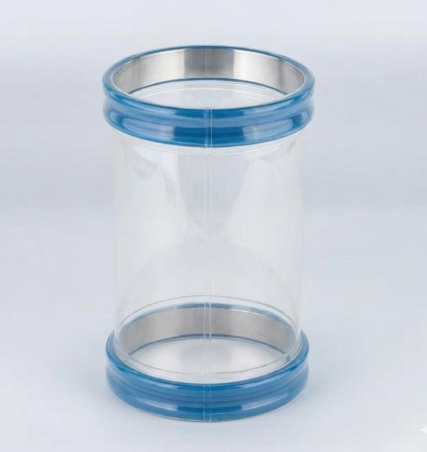
Snap-In Flexible Connector Sizing Guide: Diameter, Installation Gap & Duty Matrix
Snap-In Flexible Connector Sizing — Diameter, Installation Gap & Duty Matrix
Flexible connector sizing is governed by four interdependent variables, not a simple diameter lookup: spigot outer diameter (OD), installation gap (IG: 15–50 mm), dynamic vibration kinematics (15–30 Hz, ±3 to ±7 mm stroke), and operating pressure differential (+0.70 bar to −120 mbar). Sizing failures in powder processing lines almost always trace to an unmeasured or oversized Installation Gap, which forces the polyurethane wall to buckle into an abrasive "S-crest" fatigue fold that tears within operating days.
A flexible sleeve that mechanically "fits" between two flanges is not guaranteed to survive. Spigot diameter is merely the static starting point. The remaining three operating variables dictate whether the assembly lasts for over 1,000,000 dynamic cycles or fails prematurely due to localized mechanical shear.
1. The Four Dynamic Variables Governing Sleeve Life
To engineer an airtight, fatigue-resistant powder transfer point, document these four physical variables before specifying sleeve geometry:
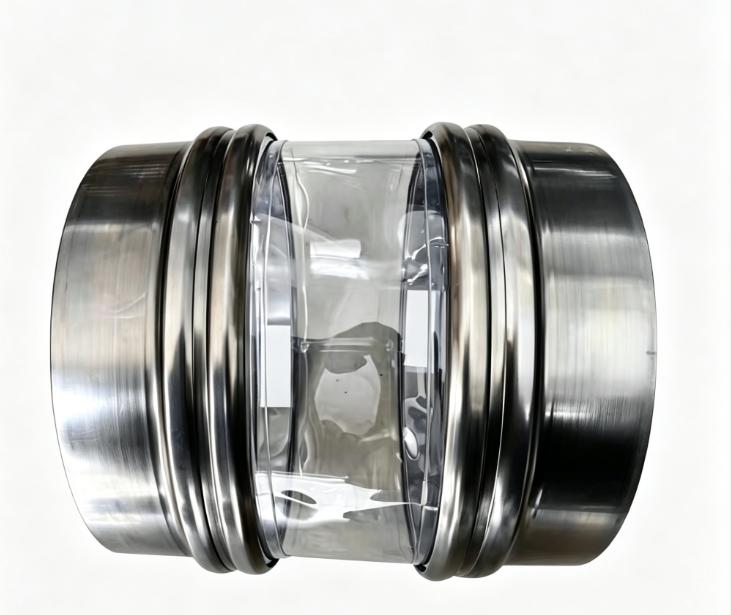
- 1. Spigot Seating Outer Diameter (OD) & Groove Geometry (mm):Measure directly at the rolled groove seating channel, not the nominal pipe size (NPS) or the outer flange edge. For example, a 300 mm nominal line with a 312 mm spigot requires an exact 312 mm snap-band cuff. Standard spigot grooves typically feature a 4.0 mm depth and 8.0 mm seat width.
- 2. Static Installation Gap (IG, in mm):The vertical or axial face-to-face distance between the stationary upper spigot lip and the oscillating lower spigot lip when the machine is at rest. This is the single most critical dimension affecting dynamic flex fatigue.
- 3. Vibratory Kinematics & Frequency (Hz / Stroke in mm):A gyratory sifter operating at 25 Hz with a ±5 mm eccentric stroke exerts severe dynamic shear on polymer chains, whereas a screw feeder at 5 Hz with ±1 mm thermal expansion imposes minimal fatigue. Material hardness and wall thickness must be matched directly to operational frequency.
- 4. Differential Pressure Envelope (bar / mbar):Positive pressure conveying pushes the sleeve wall radially outward, stressing cuff weld seams. Vacuum pneumatic conveying pulls the sleeve inward, choking bulk flow. The same diameter sleeve requires distinct structural reinforcement depending on flow direction.
2. Installation Gap Physics: The Primary Cause of Field Failures
The static Installation Gap (IG) defines the flexural geometry of the unsupported sleeve wall. Deviation from the engineered gap creates two catastrophic mechanical failure modes:
[Oversized Gap > 40 mm]       --> Wall buckles into "S-Fold" --> High-frequency self-abrasion & crease tear
[Undersized Gap < 15 mm]      --> Sleeve runs in axial tension --> Accelerated cyclic shear failure (<10^6 cycles)
[Calibrated Engineering IG]   --> Smooth, single-radius arc   --> Maximum dynamic flex fatigue life (>1,000,000 cycles)
- Failure Mode A: Oversized IG (Buckling & S-Folds):When the gap between spigots exceeds engineering limits (e.g., >40 mm on a 300 mm diameter line), the unsupported polyurethane wall buckles under vertical compression, forming a double-radius "S-curve." This secondary fold acts as an unreinforced hinge line oscillating at machine frequency (20–30 Hz), causing dynamic fatigue splits within 100–300 hours.
- Failure Mode B: Undersized IG (Static Tensile Preload):If the installation gap is narrower than the dynamic stroke of the equipment, the connector is pulled into continuous axial tension. Superimposing continuous tensile stress on top of dynamic shear forces accelerates polymer chain cleavage, drastically reducing flex life below rated endurance thresholds.
3. Engineering Sizing & Duty Matrix
Use this engineering matrix to match sleeve dimensions, wall thickness, and reinforcement to specific process kinematics:
| Sifter Operating Duty (Hz / Stroke) | Spigot Seating OD (mm) | Calibrated IG (mm) | Polymer Specification & Hardness | Wall Thickness | Structural Cuff Design |
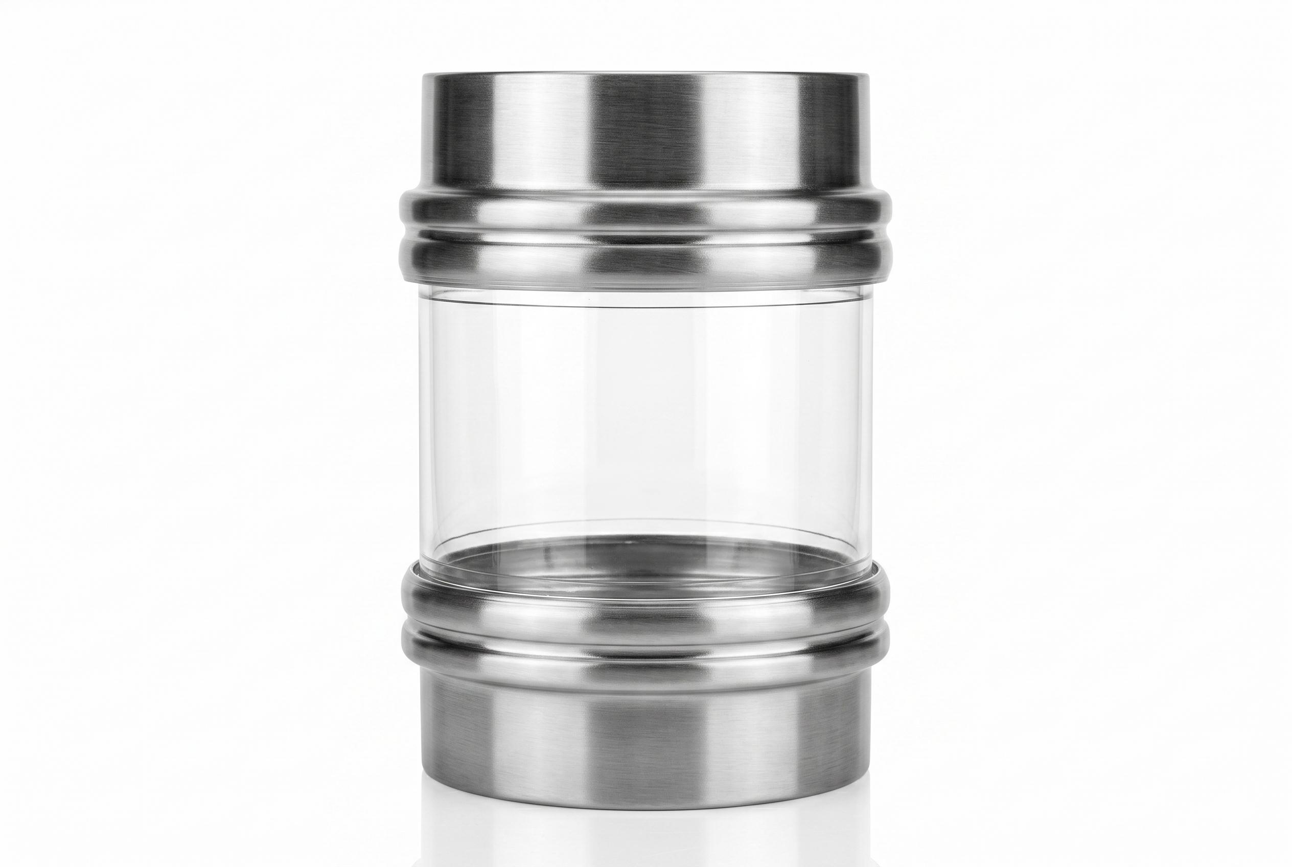
| Light Vibration / Gravity Drop (10–18 Hz / ±2 mm) | 100 – 250 mm | 15 – 25 mm | Virgin Polyether TPU (Shore A 80) | 0.8 mm | Single internal polymer snap-band, HF welded |
| Standard Vibratory Screener (18–25 Hz / ±5 mm) | 250 – 500 mm | 20 – 35 mm | Virgin Polyether TPU (Shore A 85, 110 kN/m tear) | 1.0 mm | Dual isolated cuff pockets; relocated hoop load |
| High-Stroke Gyratory Sifter (25–30 Hz / ±7 mm) | 500 – 900 mm | 30 – 50 mm | High-Tear Polyether TPU (Shore A 90) | 1.2 mm | Isolated cuff pockets + internal 316L support rings |
| Pneumatic Vacuum Line (Down to −1000 mbar) | 150 – 600 mm | 20 – 30 mm | Vacuum-rated polyether composite | 1.5 – 2.0 mm | External or internal 316L rings at 50–75 mm pitch |
| Positive Dense-Phase Blowline (Up to +0.70 bar) | 150 – 500 mm | 20 – 30 mm | High-tensile polyether TPU (Shore A 85) | 1.2 mm | Precision snap-band with outer security clamp |
| Loss-in-Weight / Micro-Dosing (Static tare requirement) | 100 – 350 mm | 25 – 40 mm | Ultra-soft Polyether TPU (Shore A 70) | 0.5 – 0.8 mm | Multi-convolution bellows; zero reaction force |
4. Pressure Boundaries: Positive vs. Vacuum Engineering
A connector engineered for positive pressure will quickly collapse under negative vacuum conveying conditions. The structural response differs fundamentally by flow regime:
Positive Pressure Containment (Up to +0.70 bar)
Internal pressure causes the flexible wall to expand radially outward. The primary stress point is transferred to the cuff-to-spigot seal and the high-frequency weld seams.
- Engineering Fix: High-frequency (HF) welded cuff pockets ensure 100% molecular bond strength. For pressures above +0.35 bar, an external secondary locking band is specified to prevent cuff roll-out.
Vacuum Transfer Lines (Down to −1000 mbar / Full Vacuum)
Negative differential pressure causes atmospheric pressure to push the unsupported polyurethane sleeve inward. An unreinforced cylindrical sleeve will collapse into a flat choke within seconds, interrupting powder flow and causing severe wall creasing.
- Engineering Fix: Integrate internal or encapsulated 316L stainless steel support rings spaced at 50 mm to 75 mm pitch intervals. The rigid rings resist inward atmospheric force while maintaining complete multi-axis flexibility. Learn more in our technical guide: Preventing Vacuum Collapse in Pneumatic Powder Lines.
5. Material Specifications & Sanitary Standards
Dimensional sizing must be paired with verified polymer science to guarantee processing safety:
- Hydrolytic Stability (CIP Washdowns): SOSHH manufactures exclusively from virgin polyether-based TPU. Unlike standard polyester TPUs that undergo rapid ester-linkage cleavage under 80 °C caustic washdowns, polyether maintains structural integrity and elasticity across continuous operating temperatures of -20 °C to +110 °C.
- Food Contact Compliance: Fully compliant with FDA 21 CFR 177.2600 (Test Report Ref: TQT4821B36E) and engineered to meet EU Framework Regulation (EC) 1935/2004 & (EU) No 10/2011. 100% free of phthalates and plasticizers. See our full guide: Is Polyurethane Food-Contact Safe?.
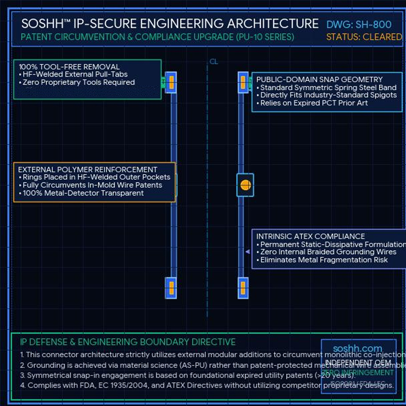
- Static Dissipation (IEC 60079-32-2): For ATEX Zones 20, 21, and 22, specify PUAS anti-static grades with surface resistivity calibrated between 10⁶ and 10⁹ Ω, eliminating electrostatic spark hazards without vulnerable external ground wires. Read Anti-Static PU Connector Engineering.
- Extreme Thermal / Chemical Duty (>150 °C): Where temperatures exceed elastomeric limits, specify CNC Machined PTFE Bellows capable of continuous service from -70 °C to +260 °C across pH 0–14.
6. Four Field Sizing Traps to Avoid
- Measuring Pipe Flanges Instead of Spigot Rims:Flange outer diameter is significantly larger than the spigot seating channel. Sizing a snap-in sleeve to flange OD results in a loose sleeve that will blow off under modest process pressure.
- Ignoring Spigot Groove Depth and Width:Standard snap-bands require specific channel clearances. If the groove is too shallow (<3.5 mm), the polymer band will not seat below the lip, creating leak paths for fluid-like powders.
- Reusing the Old Sleeve as a Sizing Template:Elastomeric connectors creep and elongate over millions of vibration cycles. Ordering a new sleeve by measuring a stretched, decommissioned part guarantees an oversized Installation Gap. Always measure steel-to-steel on the running equipment.
- Neglecting Tare Force on Weighing Equipment:Installing a stiff, thick-walled connector between a hopper and a loss-in-weight feeder transmits parasitic mechanical forces directly to load cells, inducing tare drift. Always specify multi-convolution thin-wall bellows. See Zero-Reaction-Force Weighing Bellows Guide.
Frequently Asked Questions (FAQ) — Sizing & Sifter Connectors
Q1: What is the most common sizing mistake on vibratory sifters?
A: Sizing the connector based solely on spigot diameter while failing to measure the static Installation Gap (IG). If the IG is too large, the sleeve collapses into an uncontrolled S-bend fold under 20–30 Hz oscillation, leading to premature clamp-edge tearing. Detailed failure analysis is covered in our Sifter Sleeve Tear Analysis..
Q2: How do I determine the correct Installation Gap for my equipment?
A: Measure the vertical distance between the upper and lower rigid spigot faces with the machine stationary. The optimal gap equals dynamic stroke amplitude plus a calibrated flex radius—typically 20–35 mm for standard screeners and 30–50 mm for large eccentric gyratory sifters.
Q3: Can a standard snap-in sleeve handle negative pressure in vacuum transfer?
A: No. Standard thin-wall sleeves collapse inward under vacuum levels below −100 mbar. Vacuum pneumatic transfer requires polyether TPU reinforced with internal or external 316L stainless steel support rings at 50–75 mm pitch spacing.
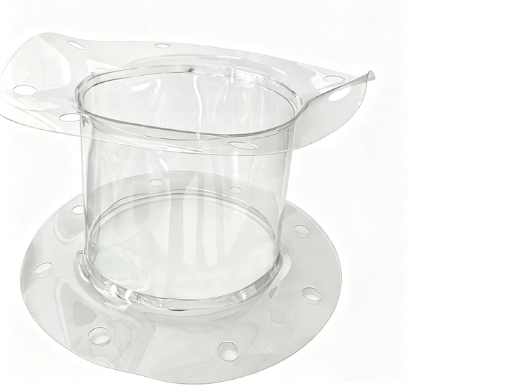
Q4: Are custom rectangular-to-round or conical transitional sleeves available?
A: Yes. Square-to-round hoppers, eccentric offsets, and conical transitions are precision CNC-cut and high-frequency welded from virgin flat sheet to millimeter specifications with zero mold or tooling charges.
Technical Sizing Checklist & Support
Before submitting an engineering inquiry or RFQ, verify the following specifications:
- [ ] Spigot outer diameter (OD) measured at seating surface (mm)
- [ ] Spigot groove depth and width verified (standard: 4.0 mm depth)
- [ ] Face-to-face Installation Gap (IG) measured on static equipment (mm)
- [ ] Sifter or screener oscillation frequency (Hz) and stroke amplitude (mm)
- [ ] Process pressure boundaries: positive, vacuum, or atmospheric (bar / mbar)
- [ ] Material compliance requirements: FDA 21 CFR 177.2600, anti-static (10⁶–10⁹ Ω), or chemical PTFE
Browse all sizing, material, and installation questions in the Flexible Connector FAQ Hub.
For custom CAD drawings, dimensional verification, or rapid 24-hour quotations, email your process parameters to amin@soshh.com.
Tags:
- TPU flexible connections
- TPU Soft Connections Manufacturer
- ATEX Rated Flexible Joints
- Connector Replacement
- Snap-in Flexible Connectors Like SOSHH
- best flexible connector for powder transfer
- snap-in powder connectors high hygiene standards
- snap-in powder connectors hygiene benefits
- FDA Food Grade PU Sleeves
- Custom PU Flexible Connectors
Related Posts